Manuals/Vacuum Devices
How Do Vacuum Devices Differ From Regular Stages and Actuators?
While Zaber's line of vacuum compatible positioners may look similar to their non-vacuum counterparts, there are several key differences that allow these devices to function at pressures down to 1 x 10⁻⁶ Torr (1.3 x 10⁻⁶ mbar) or less.
The two main challenges in operating motorized actuators and stages in a vacuum are ensuring adequate cooling and controlling outgassing.
At atmospheric pressure (760 Torr), much of the cooling of an electric motor is achieved through air currents or convection. In a vacuum chamber however, there are so few air molecules that convection can not carry significant amounts of heat away from the motor. Even in a relatively low vacuum of 1 Torr, convection accounts for less than 1% of total heat transfer. Thus, even low vacuum devices have much more challenging cooling requirements than regular stages and actuators.
These tougher cooling requirements are usually met by designing devices able to tolerate higher temperatures (which increases heat transfer rates) and by limiting motor currents to values that will not result in overheating. It is also important to mount the device to a thermally conductive surface that allows it to transfer heat outside the vacuum chamber.
The other main requirement for a vacuum compatible product is to limit the outgassing of volatile materials and trapped gasses. The consequences of outgassing can vary from the annoying (e.g. a longer pump down time) to the catastrophic (e.g. motor failure as a result of bearing lubricants vaporizing). The level of permissible outgassing depends partially on the level of vacuum the device will be operated at, though there are some minimum functional requirements - such as low vapor pressure lubricants.
Since vacuum pumps take longer to evacuate particles at lower pressures, outgassing requirements are often more stringent for high vacuum (low pressure) systems. Since outgassing is the major difference between low and high vacuum rated devices, this topic is discussed further in the section below.
Vacuum Ratings
Rating the vacuum compatibility of a device is not as straightforward as it might seem. The ultimate achievable vacuum, as well as the pumping time required to achieve this pressure, depend on the vacuum chamber, the pumping system, and the equipment inside the chamber. A high capacity pump using high conductance tubing may well be able to pump a 10-3 Torr rated actuator down to a lower pressure than a lower capacity pump could attain pumping down a 10-6 rated device.
This is not to say that these ratings are meaningless. Indeed, there are important differences between low and high vacuum devices. The main distinction being the more stringent outgassing requirements of high vacuum devices. As the pressure of a vacuum chamber is lowered, it becomes increasingly difficult to evacuate the remaining molecules. Consequently, having low outgassing equipment inside the chamber becomes increasingly important if high vacuum levels are to be attained in a reasonable amount of time.
Of course, the pump down time and the ultimate achievable vacuum are not always the only considerations in selecting vacuum stages and actuators. The outgassing of volatile condensable materials such as hydrocarbons is often more of a concern than other types of outgassing such as water vapour. Hydrocarbon vapours can condense on optical components and interfere with their operation, while water vapour does generally not condense and is effectively pumped out of the chamber.
NASA tests all materials used on spacecraft for both total mass lost through outgassing (TML) and collected volatile condensable materials (CVCM). The results of these tests are used by Zaber to select the lowest outgassing materials possible for use in our high vacuum stages and actuators.
Vaporization of volatile materials is not the only means by which gases can be introduced into the chamber. Air trapped within the surface layers of metals can be very slow to escape and can greatly increase pumping times. For this reason, high vacuum devices are rarely anodized. Air can also be trapped in blind screw holes and other closed off air pockets. Proper venting of such locations is a necessity.
Zaber Vacuum Devices: SV2 vs. SV1
The SV1 and SV2 part number suffixes designate low vacuum and high vacuum devices respectively.
SV1 devices are designed for use down to pressures of 1x10⁻³ Torr.
SV2 devices are designed for pressures down to 1x10⁻⁶ Torr.
T-LA-SV, T-MM2-V and TSB-V devices have SV1 level vacuum compatibility.
The sections below detail some of the differences between these two classes of vacuum products.
Motors
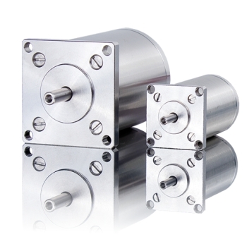
Both SV1 and SV2 devices use specially designed vacuum stepper motors. SV1 motors are designed to be low outgassing down to 10-3 Torr while SV2 motors are designed to be low outgassing down to pressures of 10-6 Torr.
Special note on T-NA vacuum motors: The motors used on both the SV1 and SV2 versions of the T-NA actuators are treated with a black electrophoresis coating. This is not anodizing and does not trap gasses within the surface of the material.
Fasteners
Vented, stainless steel screws are used in all blind holes on SV1 and SV2 vacuum devices.
Circuit Boards
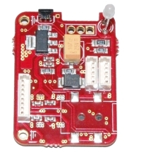
The circuit boards used in both SV1 and SV2 vacuum devices are specifically designed to be fully functional and low outgassing in a vacuum chamber. The circuit boards in our vacuum devices are specially treated to further reduce outgassing.
Assembly Procedures
SV2 Vacuum devices are assembled in a class 100 (ISO class 5) cleanroom. Prior to assembly all parts are cleaned either ultrasonically or by hand using isopropyl alcohol. Following cleaning, the parts do not leave the cleanroom and they are not handled with bare hands.
SV1 Vacuum devices are assembled following our regular assembly procedures.
Packaging
SV2 vacuum devices are packaged in Ultra Low Outgassing (ULO®) polyethylene bags inside our cleanroom. The manufacturer's description of ULO® polyethylene:
Ultra Low Outgassing (ULO®) Polyethylene was engineered specifically for critical products that require packaging in a film that combines low ionic contamination and ultra low outgassing. ULO® Poly packaging film has excellent handling characteristics and an extremely clean surface. With a higher gas barrier than standard low-density poly, ULO® Poly is an excellent choice for vacuum packaging applications. Ionic contamination and outgassing results are available for registered clients.
Devices are double bagged allowing the end user to remove the outer bag prior to inserting the device into their cleanroom.
SV1 vacuum devices are packaged normally.
Setting Up Vacuum Devices
Handling
- Guidelines for handling vacuum devices:
- Do not touch vacuum device with bare hands - use cleanroom gloves.
- Keep metal particles away from the motor. It has large vent holes and contains powerful magnets. Particles can easily be drawn into the motor and will greatly decrease motor performance.
- Dirt, dust, humidity or other foreign particles that penetrate the motor housing can also degrade motor performance. Make sure the device is stored and operated only in clean environments.
- Guidelines for handling vacuum devices:
Mounting
If possible, vacuum positioners should be mounted to a thermally conductive surface to aid in heat dissipation. Preferably, there should be a conductive heat path from the positioner through to the outside of the chamber. If this is not possible, the device should be mounted to a large conductive surface within the chamber. This will help cooling by increasing the rate of radiative heat transfer.
Temperature monitoring
A K-type thermocouple may be mounted to the stage to monitor temperature in order to reduce the risk of overheating. See the product manual for your vacuum device for the optimal mounting location for the thermocouple.
Vacuum Baking
Vacuum stages can be vacuum baked to reduce pump down time and reduce outgassing. Heat device to its recommended bake-out temperature at a vacuum of less than 10^-3 Torr for a period of several hours. Allowable bake-out temperatures differ between devices. All X-series vacuum devices can be baked to 80 °C. Check the table below for the maximum baking temperature for your device. Do not exceed the maximum listed temperature. There are polymer based components in many of the devices and these can be permanently damaged by overheating.
| Device | Max. Bake-out Temperature (°C) |
|---|---|
| X-Series | 80 |
| T-LSM-SV1 | 80 |
| T-LSM-SV2 | 80 |
| T-NA-SV1 | 110 |
| T-NA-SV2 | 110 |
Wiring/Feedthroughs
SV1 and SV2 vacuum devices are supplied with twisted signal wires and standard serial port connectors. The wires must be cut and soldered to a vacuum feed-through before the device can be operated inside a vacuum chamber.
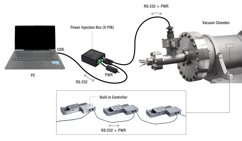
Two or more devices can be daisy chained inside a vacuum chamber, eliminating the need for extra feed-throughs. If this is to be done, it is recommended that the connectors be removed and the signal wires soldered directly from one device to the next in the chain. The wire colours should be matching.
See the wiring diagram below for the recommended connection of vacuum devices.
Powering Devices
Power to vacuum devices is transmitted through the data cables, eliminating the need for extra feed-throughs.
Powering X-Series Vacuum Devices
Only a 4 pin feed-through is required to operate multiple Zaber X-series positioners in a vacuum chamber.
The X-PIB (pictured) is required to splice the power into the data cable - it is connected to the data and power cables outside the vacuum chamber.
Powering T-Series Vacuum Devices
Only a 4 pin feed-through is required to operate multiple Zaber T-series positioners in a vacuum chamber.
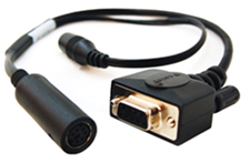
The T-DSUB9-P (pictured) is required to splice the power into the data cable - it is connected to the data cable outside the vacuum chamber.
Operating Devices
Current Settings
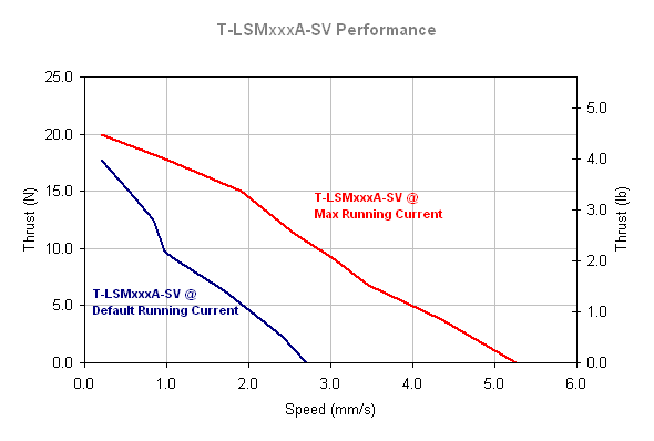
The default running currents on Zaber vacuum devices are set low enough that even prolonged operation will not damage the motor or controller. Due to the above mentioned cooling challenges of vacuum, this means that the thrust and speed performance of these devices is less than their non-vacuum counterparts.
If you are not going to be operating your vacuum device continuously for long periods of time and need some extra thrust or speed, it is possible to increase the running current of your device. If you choose to do this, keep in mind that for a given running current setting, the actual current draw (and heating) of the device will be greater at low speeds than at high speeds. As the motor speed increases, induced voltage, or back emf, acts to reduce the current flowing through the windings. Check the manual for your device for more specific running current recommendations.
It is good practice to reduce the hold current as much as is practical for vacuum devices. Positioners with an A pitch leadscrew often do not need a hold current at all to maintain their position. Reducing the hold current is an easy way to reduce the heat generated by your vacuum stage or actuator.
Duty Cycle
In the interest of reducing the heat generated by your vacuum device, it is recommended that you minimize the time that the device is moving as much as possible. For example, moving between two points at high speed will generate much less heat than moving between the same two points slowly.


