T-Series/RS-232 Communications Protocol/motion products
Control Through The RS-232 Serial Port
All T-Series devices use the same RS232 communications protocol. Your communications settings must be: 9600 baud, no hand shaking, 8 data bits, no parity, one stop bit. The yellow LED will light when there is activity on the RS232 lines. You may use this feature to determine which COM port you are connected to. We recommend using the Zaber Console that you can download from our web site. The source code is also available for you to use as an example for writing your own custom code. See the troubleshooting section later in this manual if you have trouble communicating with the device.
Important: The first time you connect a device to your computer you must issue a renumber instruction to assign each device a unique identifier. This should be done after all the devices in the daisy-chain are powered up. In older firmware versions (prior to version 5xx) you must issue a renumber instruction after each powerup. In firmware 5xx and up, the device number is stored in non-volatile memory and will persist after powerdown, so you need only issue the renumber instruction when you add new devices to the chain, or rearrange the order of the devices, however it does no harm to issue the renumber instruction after every powerup. You must not transmit any instructions while the chain is renumbering or the renumbering routine may be corrupted. Renumbering takes less than a second, after which you may start issuing instructions over the RS232 connection.
All instructions consist of a group of 6 bytes. They must be transmitted with less than 10 ms between each byte. If the device has received less than 6 bytes and then a period longer than 10 ms passes, it ignores the bytes already received. We recommend that your software behave similarly when receiving data from the devices, especially in a noisy environment like a pulsed laser lab.
The following table shows the instruction format:
- Byte 1 - Device #
- Byte 2 - Command #
- Byte 3 - Data - Least Significant Byte (LSB)
- Byte 4 - Data
- Byte 5 - Data
- Byte 6 - Data - Most Significant Byte (MSB)
The first byte is the device number in the daisy-chain. Device number 1 is the closest device to the computer and device number 2 is next and so on. If the number 0 is used, all the devices in the chain will process the accompanying command simultaneously.
The second byte is the command number. Bytes 3, 4, 5, and 6 are data in long integer, 2’s complement format with the least significant byte transmitted first. How the command data are interpreted depends on the command. Complete details are given in the command reference on the following page.
Examples
- All devices renumber: 0, 2, 0, 0, 0, 0
- All devices home: 0, 1, 0, 0, 0, 0
- All devices return firmware version: 0, 51, 0, 0, 0, 0
- Device 1 move to an absolute position (command 20) of 257 microsteps: 1, 20, 1, 1, 0, 0
- Device 2 move to a relative position (command 21) of -1 microstep: 2, 21, 255, 255, 255, 255
Most instructions cause the device to reply with a return code. It is also a group of 6 bytes. The first byte is the device #. Byte #2 is the instruction just completed or 255 (0xFF) if an error occurs. Bytes 3, 4, 5 and 6 are data bytes in the same format as the instruction command data.
Data Conversion Algorithms
If you are writing software to control Zaber products, you'll likely need to generate data bytes 3 through 6 from a single data value, or vise versa. The following pseudo-code can be used as a model.
Converting command data into command bytes to send to Zaber products
If Cmd_Data < 0 then Cmd_Data = 256^4 + Cmd_Data                                        'Handles negative data

Cmd_Byte_6 = Cmd_Data / 256^3

Cmd_Data   = Cmd_Data - 256^3 * Cmd_Byte_6

Cmd_Byte_5 = Cmd_Data / 256^2

Cmd_Data   = Cmd_Data - 256^2 * Cmd_Byte_5

Cmd_Byte_4 = Cmd_Data / 256

Cmd_Data   = Cmd_Data - 256   * Cmd_Byte_4

Cmd_Byte 3 = Cmd_Data
Converting reply bytes into a single reply data value
Reply_Data = 256^3 * Rpl_Byte 6 + 256^2 * Rpl_Byte_5 + 256 * Rpl_Byte_4 + Rpl_Byte_3

If Rpl_Byte_6 > 127 then Reply_Data = Reply_Data - 256^4                                'Handles negative data
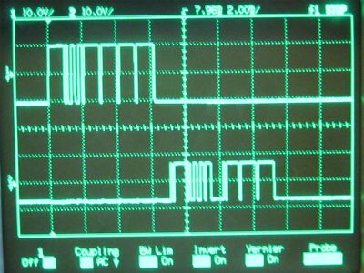
Sample Waveforms
If you are designing hardware to interface with Zaber products, it may be useful to see some sample waveforms.


