Manuals/X-FWR-E/FW6

Disclaimer
Zaber’s products are not intended for use in any critical medical, aviation, or military applications or situations where a product's use or failure could cause personal injury, death, or damage to property. Zaber disclaims any warranty of fitness for a particular purpose. The user of this product agrees to Zaber's general terms and conditions of sale.
Precautions
Zaber’s motion control devices are precision instruments and must be handled with care. In particular, moving parts must be treated with care. Avoid axial loads in excess of the rated thrust load, axial and radial impact, dust and other contaminants and damage to the drive components. These will reduce the performance of the device below stated specifications.
Device Resolution
For the X-FWR-E filter wheel, changing the device resolution (T:37) from default is not recommended. Some possible resolution settings will result in a rounding error for the distance between optic positions, which could result in misalignment of the optics over multiple revolutions of the wheel.
Conventions used throughout this document
- Fixed width type indicates communication to and from a device. The ↵ symbol indicates a carriage return, which can be achieved by pressing enter when using a terminal program.
- An ASCII command followed by (T:xx) indicates a legacy T-Series Binary Protocol command that achieves the same result. For example,
- move abs 10000 (T:20:10000) shows that a move abs ASCII command can also be achieved with Binary command number 20.
- Not all ASCII commands have an equivalent Binary counterpart.
Quick Tutorial
We recommend using Zaber Launcher to communicate with the device(s). For other software options, see the Software page. Please refer to the ASCII Protocol Manual and/or Binary Protocol Manual for more detailed information on the available commands.
Initial Set-up

- Daisy chain all integrated devices together using the RS-232 "Prev" and "Next" connectors (see Daisy-Chaining Devices for more details). Next, supply power to one or more devices. Many products share power through the daisy-chain cables. The power indicator on each should light up.
- Turn the knob to move a positioner. Most positioners will only move in one direction until they reach a home sensor at one limit of travel. Then they will move in both directions over full travel.
- Download and install Zaber Launcher. Start Zaber Launcher.
- Create a New Connection and select the communications port the first controller is connected to. For instructions on how to find the available communication ports on your system, please refer to: Appendix A - Available Communications Ports.
- If multiple devices are detected and there are conflicting device numbers, Zaber Launcher will renumber them or you can renumber (T:2) them as desired. The first device in the chain (closest to the computer) will become Device 1, the next will become Device 2, and so on.
Initialization
Every time the device is powered up or reset, the positioner should be returned to the home position. This is achieved by sending the home (T:1) command to the individual unit or all units. Until this is done, most positioners will only allow motion in one direction, towards the sensor.
If it is not possible in your application to home the positioner after every power-up, see the tools parking (T:65) command. Parking allows the device to be turned off and then used at a later time without first having to home the axes.
Using the Device
Several commonly used ASCII commands, and their Binary equivalents, are shown below. For a full list of available commands, please refer to the Command Reference section below.
| Command | Description |
|---|---|
| /1 1 get pos↵ (T:60) | Query the current position of Device #1 Axis #1. |
| /1 1 move abs 10000↵ (T:20:10000) | Move Device #1, Axis #1 to position 10000 microsteps. |
| /2 1 move rel -12800↵ (T:21:-12800) | Move Device #2, Axis #1 in the negative direction by 12800 microsteps. |
| /1 stop↵ (T:23) | Decelerate and stop ALL axes on Device 1. An axis number of 0 or no axis number implies all axes on the device, or the device itself. |
| /move vel 153600↵ (T:22:153600) | Move ALL devices and ALL axes in the positive direction at the speed 153600. A device address of 0 or no device address implies all devices in the chain. |
Modifying Device Settings
Here are some examples if you would like to customize particular device settings. Refer to the ASCII Settings or Command Reference section for detailed descriptions of each setting.
| Command | Description |
|---|---|
| /1 set maxspeed 100000↵ (T:42:100000) | Set the speed of all axes on the device. |
| /1 get maxspeed↵ (T:53:42) | Query the axes' speed. |
| /1 system restore↵ (T:36) | Restore all the settings of Device 1 to the default. |
Built-In Help
Zaber X-Series devices feature a built-in help guide, providing a quick and easy reference for all Commands and Settings that the device has. To access the help, send: /1 help↵ (for help with Device 1). The device number must be specified in the help command. This feature is only available in the ASCII protocol.
The device will respond with a detailed description on how to access specific information about commands and replies, as shown below:
@01 0 OK IDLE WR 0
#01 0 COMMAND USAGE:
#01 0  '/stop'     stop all devices
#01 0  '/1 stop'   stop device number 1
#01 0  '/1 2 stop'   stop device number 1 axis number 2
#01 0
#01 0 Type '/help commands' for a list of all top-level commands.
#01 0 Type '/help reply' for a quick reference on reply messages.
#01 0 Visit www.zaber.com/support for complete instruction manuals.
To access help for a specific command, for example the move command, send:
/1 help move↵
@01 0 OK IDLE -- 0
#01 0 move abs {x}             Move to absolute position
#01 0 move rel {x}             Move by relative position
#01 0 move vel {x}             Move at constant velocity
#01 0 move min                 Move to minimum position
#01 0 move max                 Move to maximum position
Device Overview
Connectors
All images are shown looking into the device.
Power

|
Pin | Description |
|---|---|---|
| 1 | 24 - 48 V | |
| 2 | Device GND |
Note: This product requires a CE/UL approved AC/DC power converter such as Zaber's PS13S, PS14S or PS15S with a DC cord of at most 3 m.
Note: As of February 2022, the power supplies Zaber provides are isolated and thus the device is not connected to Earth ground. Prior to 2022, most power supplies were non-isolated. Isolated units can be distinguished by the "S" suffix in their Zaber part number (eg. PS14S), which is marked on the label on the bottom of the power supply.
RS-232 Communications

|
Pin | Previous | Next |
|---|---|---|---|
| 1 | Power | Power | |
| 2 | Ground | Ground | |
| 3 | Receive | Transmit | |
| 4 | Transmit | Receive |
Default Settings:
- Baud Rate: 115200
- Protocol: Zaber ASCII
Specifications
- Supported Protocols: Zaber ASCII, Zaber Binary
- Supported Baudrates: 9600, 19200, 38400, 57600, 115200
- Bits: 8
- Parity: None
- Stop Bits: 1
- Flow Control: None
Other Connectors
For any connections not described in this document, cables should be limited to a length of 3 m.
Indicators
- Green - Power
- On: Controller is operational.
- Blinking at 2Hz: The power supply voltage or device temperature is out of range.
- Fading in and out slowly: The device is parked. See the tools parking (T:65) command.
- Red - Error
- On/blinking: Device has lost its settings, or an error has occurred. Please contact Zaber Technical Support.
- Yellow - Communication/Busy
- On: Device is moving, or data is being transferred.
- Blinking: Device is under manual control via the knob (in Velocity mode). The blinking rate is proportional to movement speed.
- Blinking at fixed rate: Packet corruption has occurred for ASCII commands sent with a checksum.
- Blue - Slip/Stall
- On: The device is slipping.
- On-Off cycle every 2 sec: The device has stalled and stopped.
- Flashes: The stationary device has been forced out of position (2 short flashes every 1 sec), or the encoder has encountered a read error and raised the FQ warning flag (5 short flashes every 2 sec).
Installation
The X-FWR-E can be connected to a computer as follows:
- Either plug the M8 to D-SUB serial adaptor (X-SDC) into the computer's serial port, or the M8 to USB adaptor (X-USBDC) into one of your computer's USB ports, then attach the device to the adaptor. For the USB adaptor, new computers will often be able to install the necessary drivers automatically when the cable is plugged in for the first time. If the computer reports that the driver installation was unsuccessful, you can download the drivers for Windows, Mac, or Linux here. Installation instructions and troubleshooting information are available for each operating system here. You may need to use a cable extension to reach your computer. There is no need to power-down or reboot the computer.
- Connect the power plug of your power supply to the power connector of the unit. The green LED should light up indicating the unit has power.
- Additional devices can simply be daisy-chained to the first. See Daisy-Chaining Devices below.
- Install software from the Software page. For the initial setup, using Zaber Launcher is recommended.

As a simple first test, try entering:
The parameter of 10000 in the move command above specifies 10000 microsteps. To see the microstep size (default resolution) for the positioner and how it translates to displacement, first go to the product overview page, find your product, click through to the product's webpage, and click on the "Series Specs" tab. The microstep size (default resolution) will be shown in the list of product specs either in the "Group Specifications" section or the "Comparison" section.
Daisy-Chaining Devices
Multiple devices can be connected together in a chain through the Prev and Next connectors. This allows any number of devices to be controlled from a single connection to a computer, reducing cabling demands. In addition, X-Series devices carry power through the daisy chain, so in most cases a power supply only needs to be connected to one device in the chain. Whenever a device is added or removed from a chain, a renumber (T:2) command should be sent to prevent device address conflicts.
Note: Daisy-chaining devices with cable lengths exceeding 8 m (25 ft) is not recommended.

To daisy-chain X-Series devices with T-Series and A-Series devices:
- Ensure all devices are set to the same communication protocol and baud rate before connecting them. If any T-Series devices will be in the chain, then the communication protocol must be Binary at 9600 baud rate.
- Connect any X-Series devices at the start of the chain (closest to the computer). This configuration will reduce the number of adaptor cables required.
- Connect a T-XDC (or S-XDC for daisy-chaining an A-MCB2) adaptor cable to the Next port of the last X-Series device in the chain, and to the Prev port of the T-Series or A-Series device.
- Power supplied to an X-Series device will not be transmitted to any T-Series or A-Series devices in the chain.
- Contact Zaber Technical Support for assistance selecting connecting cables when daisy-chaining multiple series.
Physical Installation
Mounting the Device
To mount the X-FWR-E filter wheel to an optical breadboard, a single optic post can be used as shown. Alternatively, using the AP134 post mounts, the device can be mounted to two posts either horizontally or vertically.
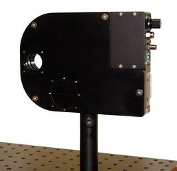
Mounting example using a single metric optical post to provided M6 threaded hole.

Mounting example using the AP134 post mount adaptors.
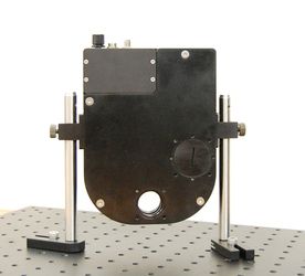
Mounting example using the AP134 post mount adaptors and optical mounting feet.


Exchanging Filter Holders

Remove the X-FWR-E housing lid using a 2.5mm hex key to remove the four cover screws.
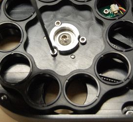
Use the 2.5mm hex key to remove the three screws holding the filter holder and slide the holder upwards and out of the case.

Place the new filter holder in position, ensuring that the two dowel pins and three screw holes line up. Tighten the three M3 screws firmly to hold the new wheel in place and prevent the screws from loosening during operation. Re-install the housing lid. If the new holder fits filters of a different size, ensure the correct apertures are open and the covers are installed on the unused aperture size.
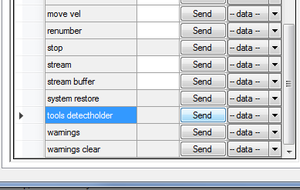
To update the settings for the X-FWR-E filter wheel for your newly installed filter holder, send the tools detectholder command to automatically configure the device. You can also manually set the filter holder ID by sending set filter.holderid (T:81) with the ID value for your installed wheel.


Optic Installation
Optics can be installed in to the filter holders using the provided retaining rings. To access the filter holder, remove the housing lid using a 2.5mm hex key.
Restoring Settings or Updating Firmware
When new firmware is installed on the X-FWR-E, or a restore settings command is sent, the settings for the installed filter holder may be lost. You can send the tools detectholder command to automatically re-configure the device or set the filter holder ID by sending set filter.holderid (T:81) with the ID value for your installed wheel.
Manual Control
Most X-Series motion control products have an integrated, depressible knob with 20 detents per revolution, allowing axes to be controlled without the use of a computer. There are two manual movement modes available: Velocity and Displacement. Switch between these modes by holding down the knob for 1 second or by configuring the knob.mode (T:109) setting.
On power-up, the axis will only travel towards the motor from its start-up position until the home position is reached. Once the axis has been homed, the full range of travel becomes available.
Velocity Mode
Turn the knob clockwise to move the axis in the positive direction (extend) or counter-clockwise for negative direction (retract). Each detent of the knob increases the speed of the carriage.
There are 16 speeds in each direction. The velocity profile and maximum speed can be configured via the knob.speedprofile (T:112) and knob.maxspeed (T:111) settings. The axis stops and resets the knob upon arriving at the end of travel.
Displacement Mode
Turn the knob clockwise to move the axis in the positive direction (extend), counter-clockwise for negative direction (retract). Each detent of the knob moves the axis a fixed number of microsteps, specified by the knob.distance (T:110) setting. If knob.distance (T:110) is set to 0, each detent of the knob will move to the next index position, similar to move index (T:78) movements. The axis moves at the speed specified by the maxspeed (T:42) setting, or the slower of maxspeed (T:42) and limit.approach.maxspeed (T:41) if the axis has not been homed. If there are fewer than knob.distance (T:110) microsteps to the end of travel and another move is requested, the axis will move to the end of travel and then stop.
Summary of knob functionality
- Turning the knob:
- Moves the axis in the direction of knob turn.
- Pressing the knob:
- Pressing and holding the knob for 1 sec:
- Toggles between Velocity Mode and Displacement Mode.
Trajectory Control and Behaviour
This section describes the behaviour of the axis trajectory when a movement command is issued.
Software Position Limits
The travel range of the axis is limited by the Minimum Position and Maximum Position settings. The factory settings for the axis are configured to match the physical travel range. If a customized range is desired, it can be changed by configuring the limit.min (T:106) and limit.max (T:44) settings to appropriate values.
- Minimum Position
- When the Current Position is less than the Minimum Position value, the axis cannot move in the negative direction(towards the motor).
- Maximum Position
- When the Current Position is greater than the Maximum Position value, the axis cannot move in the positive direction(towards the motor).
Movement Speed
The movement speed of the axis depends on axis status and various speed settings. If the axis has not been initialized by the home (T:1) command or by moving towards the home end of the axis, movement speed will be constrained to fail-safe values. The home status of the axis can be determined by reading the limit.sensor.triggered (T:53) setting (the binary command additionally requires a value of 103).
Movement speed of the axis is specified below:
- move vel (T:22)
- The axis will move at the specified speed regardless of home status.
- Knob movement in Velocity Mode
- The axis will move at the specified speed regardless of home status.
- The speed is specified by the knob.speedprofile (T:112) and knob.maxspeed (T:111) settings.
- Other movement commands - when the axis has not been homed
- The axis will move at the slower of the maxspeed (T:42) and limit.approach.maxspeed (T:41) settings.
- Other movement commands - when the axis has been homed
- The axis will move at the speed specified by the maxspeed (T:42) setting.
Quick Command Reference
All X-Series devices ship with the ASCII Protocol enabled by default but the Binary Protocol is also supported.
ASCII Protocol
The following table offers a quick command and setting reference for the X-FWR-E. Follow the links to view a detailed description of each instruction or refer to the ASCII Protocol Manual.
Quick Commands
Parameters in square brackets, e.g. [clr], indicate that the parameter is optional.
Parameters in italics, e.g. value, indicate that data, typically a number, needs to be provided.
Parameters separated by a pipe, e.g. abs|rel, indicate that one of the parameters in the set need to be provided.
| Command | Scope | Parameter(s) | Returns | Firmware Versions | Description |
|---|---|---|---|---|---|
| estop | Axis | 0 | 6.06+ | Instantly stops motorized movement. | |
| get | Device and Axis | setting | value | 6.06+ | Retrieves the current value of the device or axis setting. |
| help | Device | commands reply warnflags enums command ... enum |
0 | 6.06+ | Displays the help information for the system. |
| home | Axis | 0 | 6.06+ | Moves the axis to the home position. | |
| move | Axis |
abs|rel|vel value |
0 | 6.06+ | Moves the axis to various positions along its travel. |
| renumber | Device | value | 0 | 6.06+ | Renumbers all devices in the chain. |
| set | Device and Axis | setting value | 0 | 6.06+ | Sets the device or axis setting setting to the value. |
| stop | Axis | 0 | 6.06+ | Decelerates the axis and brings it to a halt. | |
| stream | Device | Refer to the documentation | Refer to the documentation | 6.12+ | Performs an action related to streamed, interpolated motion. |
| system reset | Device | 0 | 6.06+ | Resets the device, as it would appear after power up. | |
| system restore | Device | 0 | 6.06+ | Restores common device settings to their default values. | |
| tools detectholder | Axis | 0 | 6.22+ | Detects the currently installed filter holder. | |
| tools echo | Device | (message) |
0 | 6.06+ | Echoes the provided message (if any) back to the user. |
| tools gotolimit | Axis | limit dir action update | 0 | 6.06+ | Moves the axis to a limit sensor and performs the provided actions. |
| tools parking | Device |
state|park|unpark |
0|1 |
6.06+ | Parking allows the device to be turned off and used at a later time without first having to home. |
| tools setcomm | Device | rs232baud protocol | 0 | 6.06+ | Sets RS232 baud rate and communication protocol for RS232 and USB. |
| tools storepos | Axis |
number [position|current] |
0|position |
6.06+ | Stores a number of positions for easy movement. |
| trigger | Device | Refer to the documentation | 0 | 6.06+ | Configures actions to be performed on the device when a certain condition is met. |
| warnings | Axis | [clear] |
0 | 6.06+ | Displays the active device and axis warnings, optionally clearing them if applicable. |
Quick Device Settings
The settings listed below can be inspected and modified with the get and set commands described above.
| Setting | Scope | Writable | Firmware Versions | Description |
|---|---|---|---|---|
| accel | Axis | Yes | 6.06+ | Sets the acceleration used to modify the speed. |
| cloop.counts | Axis | Yes | 6.06+ | The number of counts generated by the encoder for one full revolution. |
| cloop.displace.tolerance | Axis | Yes | 6.19+ | The minimum deviation in the position of a stationary axis that will register as a displacement. |
| cloop.mode | Axis | Yes | 6.06+ | The closed-loop (slip, stall, and displacement detection and recovery) control mode. |
| cloop.stalltimeout | Axis | Yes | 6.06+ | The amount of time to wait after a stall/displacement condition, in milliseconds. |
| cloop.steps | Axis | Yes | 6.06+ | The number of full steps required for the motor to complete one revolution. |
| comm.address | Device | Yes | 6.06+ | The device address. |
| comm.alert | Device | Yes | 6.06+ | The device will send alert messages when this setting is 1. |
| comm.checksum | Device | Yes | 6.06+ | The device includes checksums in its messages if this setting is set to 1. |
| comm.protocol | Device | Yes | 6.06+ | The communications protocol used by the device on the current interface. |
| comm.rs232.baud | Device | Yes | 6.06+ | The baud rate used by RS232 Prev and Next interfaces. |
| comm.rs232.protocol | Device | Yes | 6.09+ | The protocol used by RS232 Prev and Next interfaces. |
| deviceid | Device | No | 6.06+ | The device ID for the unit. |
| driver.current.hold | Axis | Yes | 6.06+ | Current used to hold the motor in position, in 20 mA DC increments. |
| driver.current.max | Axis | No | 6.16+ | Maximum legal value of driver.current.hold and driver.current.run. |
| driver.current.run | Axis | Yes | 6.06+ | Current used to drive the motor, in 14.1 mA RMS (20 mA peak) increments. |
| driver.temperature | Axis | No | 6.06+ | The current temperature of the axis driver, in degrees Celsius. |
| encoder.count | Axis | Yes | 6.06+ | The recorded counts of the axis encoder. |
| encoder.error | Axis | No | 6.17+ | Position error measured by encoder. |
| encoder.index.count | Axis | Yes | 6.06+ | The recorded counts of the axis encoder index pulse. |
| encoder.pos | Axis | No | 6.17+ | Position measured by encoder. |
| filter.holderid | Axis | Yes | 6.22+ | The ID of the installed filter holder. |
| knob.dir | Axis | Yes | 6.06+ | Sets the movement direction for the knob. |
| knob.distance | Axis | Yes | 6.06+ | Sets how far the device moves with each step of the knob in displacement mode, in units of microsteps. |
| knob.enable | Axis | Yes | 6.06+ | Disable the use of the knob when set to 0. |
| knob.maxspeed | Axis | Yes | 6.06+ | The maximum speed that can be reached using the knob in velocity mode. |
| knob.mode | Axis | Yes | 6.06+ | Sets the mode of the manual control knob. |
| knob.speedprofile | Axis | Yes | 6.06+ | Sets the profile to be used per increment when in velocity mode. |
| limit.approach.maxspeed | Axis | Yes | 6.06+ | Maximum speed used when approaching a limit sensor. |
| limit.cycle.dist | Axis | Yes | 6.20+ | The length of one full rotation. |
| limit.detect.decelonly | Axis | Yes | 6.06+ | Deceleration used when stopping after a limit sensor has triggered. |
| limit.detect.maxspeed | Axis | Yes | 6.06+ | Maximum speed used when moving away from a limit sensor. |
| limit.home.action | Axis | Yes | 6.06+ | Automatic limit switch action. |
| limit.home.pos | Axis | Yes | 6.06+ | The updated position of the sensor, when triggered. |
| limit.home.posupdate | Axis | Yes | 6.06+ | Position update to occur when sensor is triggered. |
| limit.home.preset | Axis | Yes | 6.06+ | The default position of the home sensor. |
| limit.home.state | Axis | No | 6.06+ | The state of the home sensor. |
| limit.home.triggered | Axis | No | 6.06+ | Whether the home sensor has been triggered previously. |
| limit.max | Axis | Yes | 6.06+ | The maximum position the device can move to, measured in microsteps. |
| limit.min | Axis | Yes | 6.06+ | The minimum position the device can move to, measured in microsteps. |
| limit.start.pos | Axis | Yes | 6.19+ | Start up position of the axis. |
| maxspeed | Axis | Yes | 6.06+ | The maximum speed the device moves at. |
| motion.accelonly | Axis | Yes | 6.06+ | Sets the acceleration used to increase the speed. |
| motion.decelonly | Axis | Yes | 6.06+ | Sets the deceleration used when decreasing the speed. |
| motion.index.dist | Axis | Yes | 6.21+ | The distance between consecutive index positions. |
| motion.index.num | Axis | No | 6.22+ | The current index number. |
| pos | Axis | Yes | 6.06+ | The current absolute position of the device. |
| resolution | Axis | Yes | 6.06+ | Microstep resolution |
| stream.numbufs | Device | No | 6.14+ | The number of stream buffers provided in the device. |
| stream.numstreams | Device | No | 6.14+ | The number of streams provided in the device. |
| system.access | Device | Yes | 6.06+ | Sets the access level of the user. |
| system.axiscount | Device | No | 6.06+ | The number of axes in the device. |
| system.led.enable | Device | Yes | 6.06+ | Enables the front panel LEDs. |
| system.serial | Device | No | 6.15+ | The serial number of the device. |
| system.voltage | Device | No | 6.06+ | The voltage being applied to the device. |
| version | Device | No | 6.06+ | The firmware version of the device. |
| version.build | Device | No | 6.17+ | The build number of the device’s firmware. |
Binary Protocol
The following table offers a quick command reference for the X-FWR-E. For convenience, you may sort the table below by instruction name, command number, or reply number. Follow the links to view a detailed description of each instruction or refer to the Binary Protocol Manual.
| Instruction Name | Command# | Command Data | Command Type | Reply Data |
|---|---|---|---|---|
| Reset | 0 | Ignored | Command | None |
| Home | 1 | Ignored | Command | Final position (in this case 0) |
| Renumber* | 2 | Ignored | Command | Device ID |
| Read Register | 5 | Register Address | Command | Data |
| Set Active Register | 6 | Register Address | Setting | Register Address |
| Write Register | 7 | Data | Command | Data |
| Move Tracking | 8 | n/a | Reply | Tracking Position |
| Limit Active | 9 | n/a | Reply | Final Position |
| Manual Move Tracking | 10 | n/a | Reply | Tracking Position |
| Manual Move | 11 | n/a | Reply | Final Position |
| Slip Tracking | 12 | n/a | Reply | Tracking Position |
| Unexpected Position | 13 | n/a | Reply | Final Position |
| Store Current Position* | 16 | Address | Command | Address |
| Return Stored Position | 17 | Address | Command | Stored Position |
| Move To Stored Position | 18 | Address | Command | Final Position |
| Move Absolute | 20 | Absolute Position | Command | Final Position |
| Move Relative | 21 | Relative Position | Command | Final Position |
| Move At Constant Speed | 22 | Speed | Command | Speed |
| Stop | 23 | Ignored | Command | Final Position |
| Restore Settings* | 36 | Peripheral ID | Command | Peripheral ID |
| Set Microstep Resolution* | 37 | Microsteps | Setting | Microsteps |
| Set Running Current* | 38 | Value | Setting | Value |
| Set Hold Current* | 39 | Value | Setting | Value |
| Set Device Mode* | 40 | Mode | Setting | Mode |
| Set Home Speed* | 41 | Speed | Setting | Speed |
| Set Target Speed* | 42 | Speed | Setting | Speed |
| Set Acceleration* | 43 | Acceleration | Setting | Acceleration |
| Set Maximum Position* | 44 | Range | Setting | Range |
| Set Current Position | 45 | New Position | Setting | New Position |
| Set Home Offset* | 47 | Offset | Setting | Offset |
| Set Alias Number* | 48 | Alias Number | Setting | Alias Number |
| Return Device ID | 50 | Ignored | Read-Only Setting | Device ID |
| Return Firmware Version | 51 | Ignored | Read-Only Setting | Version |
| Return Power Supply Voltage | 52 | Ignored | Read-Only Setting | Voltage |
| Return Setting | 53 | Setting Number | Command | Setting Value |
| Return Status | 54 | Ignored | Read-Only Setting | Status |
| Echo Data | 55 | Data | Command | Data |
| Return Firmware Build | 56 | Ignored | Read-Only Setting | Build Number |
| Return Current Position | 60 | Ignored | Read-Only Setting | Position |
| Return Serial Number | 63 | Ignored | Read-Only Setting | Serial Number |
| Set Park State* | 65 | Park State | Setting | Position |
| Return Digital Input Count | 67 | Ignored | Read-Only Setting | Pin Count |
| Return Digital Output Count | 70 | Ignored | Read-Only Setting | Pin Count |
| Return Analog Input Count | 75 | Ignored | Read-Only Setting | Pin Count |
| Return Analog Output Count | 77 | Ignored | Read-Only Setting | Pin Count |
| Move Index | 78 | Index Number | Command | Final Position |
| Set Index Distance | 79 | Distance | Setting | Distance |
| Set Cycle Distance | 80 | Distance | Setting | Distance |
| Set Filter Holder ID | 81 | Filter Holder ID | Setting | Filter Holder ID |
| Return Encoder Count | 82 | Ignored | Read-Only Setting | Encoder Count |
| Set Auto-Reply Disabled Mode* | 101 | Auto-Reply Mode | Setting | Auto-Reply Mode |
| Set Message ID Mode* | 102 | Message ID Mode | Setting | Message ID Mode |
| Set Home Status | 103 | Home Status | Setting | Home Status |
| Set Auto-Home Disabled Mode* | 105 | Auto-Home Disabled Mode | Setting | Auto-Home Disabled Mode |
| Set Minimum Position* | 106 | Minimum Position | Setting | Minimum Position |
| Set Knob Disabled Mode* | 107 | Knob Disabled Mode | Setting | Knob Disabled Mode |
| Set Knob Direction* | 108 | Direction | Setting | Direction |
| Set Knob Movement Mode* | 109 | Movement Mode | Setting | Movement Mode |
| Set Knob Jog Size* | 110 | Jog Size | Setting | Jog Size |
| Set Knob Velocity Scale* | 111 | Velocity Scale | Setting | Velocity Scale |
| Set Knob Velocity Profile* | 112 | Velocity Profile | Setting | Velocity Profile |
| Set Acceleration Only* | 113 | Acceleration | Setting | Acceleration |
| Set Deceleration Only* | 114 | Deceleration | Setting | Deceleration |
| Set Move Tracking Mode* | 115 | Tracking Mode | Setting | Tracking Mode |
| Set Manual Move Tracking Disabled Mode* | 116 | Tracking Mode | Setting | Tracking Mode |
| Set Move Tracking Period* | 117 | Tracking Period | Setting | Tracking Period |
| Set Closed-Loop Mode* | 118 | Closed-Loop Mode | Setting | Closed-Loop Mode |
| Set Slip Tracking Period* | 119 | Tracking Period | Setting | Tracking Period |
| Set Stall Timeout* | 120 | Timeout | Setting | Timeout |
| Set Baud Rate* | 122 | Baud Rate | Setting | Baud Rate |
| Set Protocol* | 123 | Protocol | Setting | Protocol |
| Convert To Ascii* | 124 | Baud Rate | Command | Baud Rate |
| Error | 255 | n/a | Reply | Error Code |
* The settings for these commands are saved in non-volatile memory, i.e. the setting persists even if the device is powered down. To restore all settings to factory default, use command 36.
Troubleshooting X-Series Motion Devices
The following sections contain tips for troubleshooting common problems. If the device is unable to communicate, and it is operating erratically, a manual factory reset can be performed through the following steps. Note that this will reset most settings.
- Power Off the device
- Push and hold the knob for the first Axis (if applicable)
- Power On the device
- Continue to hold the knob in until the blue LED is lit (~5 seconds), then release.
The device has been returned to its factory defaults and can be configured as per the steps in Initial Setup.
Front Panel Indicators
- Green LED On
- The device is powered on and is operating normally.
- Green LED Fades In and Out
- The device is parked.
- Issue a tools parking unpark (T:65) command, or home (T:1) the device.
- Green LED Flashes Slowly
- The operating conditions of the device are outside of the recommended range.
- This will occur when the supply voltage is either over or under the recommended range, the internal temperature has exceeded the set limit, or the driver has been disabled. Check the following:
- The input voltage is within the operational range of the device. This can be read from the device with the get system.voltage command.
- The device temperature is within range. This can be read from the device with the get system.temperature command.
- The driver is not disabled. If the driver is disabled the result of the warnings command will contain the FD flag.
- Green LED Off
- The device is not powered.
- Check the supply connections and power adaptor for correct operation.
- Red LED On or Flashing.
- A critical error has occurred.
- Please contact Zaber Technical Support.
- Blue LED On or Flashing.
- The axis has slipped or stalled.
- Please see the Slipping and Stalling section below.
- Yellow LED Always Off or Flashes but No Reply.
- There are communication errors.
- Please see the Communication Errors section below.
Manual Control
- Turning the knob either way results in no movement
- The knob may have been disabled.
- Check that the knob.enable (T:107) setting is correct.
- Restore the default parameters through the system restore (T:36) command.
- The axis won't cover the full range of travel.
- The axis hasn't been homed.
- Turn the knob anti-clockwise until the axis reaches the fully retracted position (closest to the motor). The axis will home and the full range of travel available.
Unexpected Behaviour
- The axis doesn't respond to a move command.
- The axis needs to be homed before use.
- Send the home (T:1) command.
- The axis is moving on its own and running against the ends of travel.
- The position encoder has de-synchronized.
- Reset the device by power cycling it or sending the system reset (T:0) command, then re-initialize it with the home (T:1) command.
- The axis is moving very slowly. It used to move faster.
- The speed settings may have been changed inadvertently.
- Send a system restore (T:36) command.
- The axis makes louder than normal noise during travel and is frequently slipping.
- This condition happens if the thrust needed is more than the thrust available from the axis.
- Check the following:
- The force on the axis is less than the maximum thrust.
- The voltage matches the specified voltage. Read the voltage using the get system.voltage command. Voltage less than the specified voltage for the device will reduce the positioner’s maximum thrust.
- Test the following:
- Try a slower target velocity. Stepper motors produce more thrust when moving slowly.
- Try a lower acceleration and deceleration.
- Clean the screw and lightly re-grease it with a grease that does not degrade plastics.
- The axis has repeatability errors smaller than 4 full steps.
- If steps aren't being skipped, friction or loose parts may still cause some variation when returning to a position.
- Please contact Zaber Technical Support.
- The axis doesn't cover the full range of travel, or runs into the end.
- A setting might have been inadvertently changed.
- home (T:1) the axis to see if this corrects the behaviour.
- Send a system restore (T:36) command.
Communication Errors
- There is no communication with the device; the Yellow LED does not come on or flash.
- There are several things that should be checked:
- Make sure the correct serial port is selected. Try selecting other serial ports in the software.
- Check the baud rate, hand shaking, parity, stop bit, etc. when configuring the serial communications software. The required settings are listed in the RS-232 Communications section above.
- Make sure there are no bent pins in the ends of all the data cables
- Make sure the device is powered. The Green LED should be on.
- If the computer is a laptop running on batteries, try plugging in the power. Some laptops disable the serial ports when running on batteries.
- Make sure a null modem adaptor or cable is not being used.
- Make sure the correct adaptors(if any) are being used. Refer to the pinouts in the RS-232 Communications section above.
- If the problem was encountered when trying to control the device with custom software, try using Zaber Launcher or Zaber Console (available from the Zaber website) to verify that the hardware is functioning properly.
- Two or more devices both respond to commands sent to device 1.
- Most devices are shipped with their device number set as 1.If you connect to the devices with Zaber Launcher, it will automatically renumber them if needed. If you aren't able to install and open Zaber Launcher, send the renumber (T:2) command in the software you are using to set all of the device numbers to different values.
- The Yellow LED comes on briefly when sending a command, but the device does not move and does not reply.
- Check baud rate, hand shaking, parity, stop bit, etc. are set as per the RS-232 Communications defaults.
- The device numbers may not be what is expected, issue a renumber (T:2) command. Make sure that the computer does not transmit anything else while the devices renumber.
- If using the Binary Protocol, check the following:
- 6 bytes are transmitted and that the device number and command are valid.
- The software does not transmit any control characters such as line feed and spaces.
- That the serial port is not configured with a termination character (it often defaults to linefeed).
- If problems are encountered when using custom software, try using Zaber Launcher or Zaber Console (available from the Zaber website) to verify that the hardware works.
- The device does not behave as expected when software sends it a series of commands.
- If your computer's language and region settings are other than US English, your software may be sending non-ASCII characters or using commas instead of periods as decimal points. Try setting your computer's language to English and region to United States to see if it fixes the problem.
- Check what is being sent out of the serial port. stackoverflow.com has a list of some tools to monitor serial ports.
- In Binary mode, the device does not send replies but otherwise works.
- Auto-reply might have been disabled via T:101.
- Send a system restore (T:36) command.
- If the problem is encountered when trying to control the device with custom software:
- Use the Zaber Console (available from the Zaber website) to verify that the hardware is functioning properly.
- Make sure that the receiving part of the code or commercial package is correct.
- Check the serial port settings are correct.
- Check connectors for bent or broken pins.
- In Binary mode, the device sometimes returns fewer than 6 bytes.
- This typically indicates a problem with the serial port settings. Some serial ports are set to automatically recognize and remove specific control characters such as carriage returns when they appear in the RS-232 receive buffer.
- Check that the settings are correct and are not removing or replacing characters.
Slipping and Stalling
- The axis moves smoothly, but only moves for a short time then stops. The Blue LED is flashing but the axis is not actually slipping or stalling.
- The internal encoder counter needs to be re-initialized. Reset the device by power cycling it or sending system reset (T:0) command, then re-initialize it with the home (T:1) command.
- Ground the device and avoid operating it under statically noisy environment.
- The axis makes noise but does not move. The Blue LED is flashing.
- The axis is stalling.
- Try removing all external loads. If the axis now extends and retracts normally, the problem is excessive load. Try to reduce the load and ensure the load is less than the maximum thrust. A higher thrust or torque can be achieved by lowering the speed of the axis using the maxspeed (T:42) setting.
- If an axis is stalling with no external load at default speed and acceleration settings then it requires servicing.
Warranty and Repair
For Zaber's policies on warranty and repair, please refer to the Ordering Policies.
Standard products
Standard products are any part numbers that do not contain the suffix ENG followed by a 4 digit number. Most, but not all, standard products are listed for sale on our website. All standard Zaber products are backed by a one-month satisfaction guarantee. If you are not satisfied with your purchase, we will refund your payment minus any shipping charges. Goods must be in brand new saleable condition with no marks. Zaber products are guaranteed for one year. During this period Zaber will repair any products with faults due to manufacturing defects, free of charge.
Custom products
Custom products are any part numbers containing the suffix ENG followed by a 4 digit number. Each of these products has been designed for a custom application for a particular customer. Custom products are guaranteed for one year, unless explicitly stated otherwise. During this period Zaber will repair any products with faults due to manufacturing defects, free of charge.
How to return products
Customers with devices in need of return or repair should contact Zaber to obtain an RMA form which must be filled out and sent back to us to receive an RMA number. The RMA form contains instructions for packing and returning the device. The specified RMA number must be included on the shipment to ensure timely processing.
Email Updates
If you would like to receive our periodic email newsletter including product updates and promotions.
Contact Information
Contact Zaber Technologies Inc by any of the following methods:
| Phone | 1-604-569-3780 (direct) 1-888-276-8033 (toll free in North America) |
|---|---|
| Fax | 1-604-648-8033 |
| #2 - 605 West Kent Ave. N., Vancouver, British Columbia, Canada, V6P 6T7 | |
| Web | www.zaber.com |
| Please visit our website for up to date email contact information. |
The original instructions for this product are available at https://www.zaber.com/manuals/X-FWR-E.
Appendix A - Available Communications Ports
The following instructions outline how to find installed serial ports on your computer.
Windows
- Open Search or Run from the Start Menu or Taskbar, type "Device Manager" and press enter.
- Expand the Ports (COM & LPT) category.
- In this example there are two serial ports available (COM1 and COM15), which are both USB adaptors.


Linux
- Finding devices
- Open a terminal and execute the following command:
- dmesg | grep -E ttyU\?S↵
- The response will be similar to the following:
[ 2.029214] serial8250: ttyS0 at I/O 0x3f8 (irq = 4) is a 16550A
[ 2.432572] 00:07: ttyS0 at I/O 0x3f8 (irq = 4) is a 16550A
[ 2.468149] 0000:00:03.3: ttyS4 at I/O 0xec98 (irq = 17) is a 16550A
[ 13.514432] usb 7-2: FTDI USB Serial Device converter now attached to ttyUSB0 - This shows that there are 3 serial ports available: ttyS0, ttyS4 and ttyUSB0 (a USB adaptor)
- Checking port permissions
- Using the ports found above, execute the following command
- ls -l /dev/tty{S0, S4, USB0}↵
- The permissions, given below, show that a user has to be root or a member of the dialout group to be able to access these devices
crw-rw---- 1 root dialout 4, 64 Oct 31 06:44 /dev/ttyS0
crw-rw---- 1 root dialout 4, 68 Oct 31 06:45 /dev/ttyS4
crw-rw---- 1 root dialout 188, 0 Oct 31 07:58 /dev/ttyUSB0
- Checking group membership
- groups↵
- The output will be similar to the following:
adm cdrom sudo dip plugdev users lpadmin sambashare
Notice that dialout is not in the list - A user can be added to the dialout group with the following command
- sudo adduser $USER dialout↵
- Group membership will not take effect until the next logon.
OSX
- Finding devices
- Open a terminal and execute the following command:
- ls /dev/cu.*serial*
- The response will be similar to the following:
/dev/cu.usbserial-FTB3QAET
/dev/cu.usbserial-FTEJJ1YW - This shows that there are two serial ports available, both of which happen to be USB adaptors.
- There may be other devices that match this query, such as keyboards or some web cameras. To determine which one corresponds to your USB serial cable, try repeating the command with and without the cable connected to the computer, to see which one appears and disappears.
Appendix B - Adjusting Device Performance
For customers requiring very fast adjacent optic change times, some optimizations can be made to the device and computer settings.
COM port settings
If you are using an X-USBDC to connect the device to a computer, COM port settings on the computer may add a small delay to each movement. To check and adjust this setting, follow these steps:
Windows
- Ensure you are using a baud rate of 115200 (the default for Zaber ASCII communication).
- Open the Control Panel and Select "Device Manager".
- Under "Ports (COM & LPT)" right click on the COM for used by the device and select "Properties".
- Under the "Port Settings" tab, click "Advanced..."
- Select 1ms in the drop down menu for the "Latency Timer".
Note: If your device is connected directly to a native serial port on the computer, this delay will not be present.
Adjusting acceleration
The adjacent optic change time for the X-FWR-E filter wheel can be reduced by increasing the device acceleration. The maximum acceleration setting will depend on the running current setting, the mass of the installed optics, and the amount of vibration possible (a firmly mounted device will vibrate less). Acceleration (Accel (T:43)) setting values up to 1400 may be possible. Device running current (driver.current.run (T:38)) can be adjusted up to 100 for improved motor torque. The device may run slightly warmer with an increased running current. See the Quick Command Reference for more information on adjusting device settings.