Manuals/Binary Protocol Manual
This manual describes the binary communications protocol as supported by all of Zaber's A-Series devices. For devices with firmware version 6.06 and above, the ASCII Protocol is the recommended method of communication. See Appendix A for how to switch between these protocols.
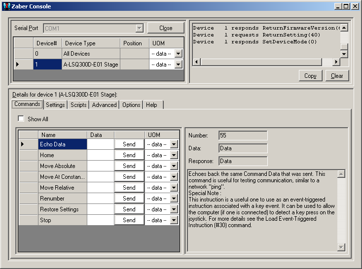
Quick Start
- Download Zaber Console from https://www.zaber.com/wiki/Software/Zaber_Console and install it.
- Switch to the Options Tab and check that the Baud Rate is set to 9600 and the Protocol to Binary.
- Select the Serial Port to use and Click the Open button. A list of attached devices will be shown.
- Switch to the Commands tab:
- Enter 0 in the box next to Renumber and press Send.
- Press the Send button next to the home command.
- Enter 10000 in the box next to Move Absolute and press send.


Serial Port Configuration
All devices using the binary protocol default to the following settings:
- Baudrate: 9600 bits/s
- Data bits: 8
- Parity bit: None
- Stop bit: 1
- Handshake/Flow control: None
Message Format
All instructions consist of a group of 6 bytes. They must be transmitted with less than 10 ms between each byte. If the device has received less than 6 bytes and then a period longer than 10 ms passes, it ignores the bytes already received. We recommend that your software behave similarly when receiving data from the devices, especially in a noisy environment like a pulsed laser lab.
The following table shows the instruction format:
- Byte 1 - Device #
- Byte 2 - Command #
- Byte 3 - Data - Least Significant Byte (LSB)
- Byte 4 - Data
- Byte 5 - Data
- Byte 6 - Data - Most Significant Byte (MSB)
The first byte is the device number in the daisy-chain. Device number 1 is the closest device to the computer and device number 2 is next and so on. If the number 0 is used, all the devices in the chain will process the accompanying command simultaneously.
The second byte is the command number. Bytes 3, 4, 5, and 6 are data in long integer, 2’s complement format with the least significant byte transmitted first. How the command data are interpreted depends on the command. Complete details are given in the command reference on the following page.
Examples
- All devices renumber: 0, 2, 0, 0, 0, 0
- All devices home: 0, 1, 0, 0, 0, 0
- All devices return firmware version: 0, 51, 0, 0, 0, 0
- Device 1 move to an absolute position (command 20) of 257 microsteps: 1, 20, 1, 1, 0, 0
- Device 2 move to a relative position (command 21) of -1 microstep: 2, 21, 255, 255, 255, 255
If you are using Zaber’s demo software, you will only see 3 entry fields: Device#, Command#, and Data. The Device# and Command# fields accept unsigned integer values while the value you enter into the Data field can be signed. The value in the data field is converted by the software to 4 separate bytes and then gets sent to the device.
Most instructions cause the device to reply with a return code. It is also a group of 6 bytes. The first byte is the device #. Byte #2 is the instruction just completed or 255 (0xFF) if an error occurs. Bytes 3, 4, 5 and 6 are data bytes in the same format as the instruction command data.
Data Conversion Algorithms
If you are writing software to control Zaber products, you'll likely need to generate data bytes 3 through 6 from a single data value, or vise versa. The following pseudo-code can be used as a model.
Converting command data into command bytes to send to Zaber products
If Cmd_Data < 0 then Cmd_Data = 256^4 + Cmd_Data                                                'Handles negative data
Cmd_Byte_6 = Cmd_Data / 256^3
Cmd_Data   = Cmd_Data - 256^3 * Cmd_Byte_6
Cmd_Byte_5 = Cmd_Data / 256^2
Cmd_Data   = Cmd_Data - 256^2 * Cmd_Byte_5
Cmd_Byte_4 = Cmd_Data / 256
Cmd_Data   = Cmd_Data - 256   * Cmd_Byte_4
Cmd_Byte 3 = Cmd_Data
Converting reply bytes into a single reply data value
Reply_Data = 256^3 * Rpl_Byte 6 + 256^2 * Rpl_Byte_5 + 256 * Rpl_Byte_4 + Rpl_Byte_3
If Rpl_Byte_6 > 127 then Reply_Data = Reply_Data - 256^4                                        'Handles negative data
Sample Waveforms
If you are designing hardware to interface with Zaber products, it may be useful to see some sample waveforms.
| This image shows an instruction (top waveform) and a reply (bottom waveform). | 
|
| This is a closeup of the instruction bytes. Note that the voltage swing of the instruction waveform is about +/-10V. This is typical of the USB to RS232 converter to which the device is connected. The instruction bytes are 0, 51, 0, 0, 0, 0 indicating the instruction: Device: All, Command: Return version, Data: 0. | 
|
| This is a closeup of the instruction byte 2. The "S" on either end represents the start and stop bits respectively. The start bit is always positive and the stop bit is always negative. The bit sequence is Start, 0, 1, 2, 3, 4, 5, 6, 7, Stop. The data is output with the least significant bit first, so the byte shown is actually 00110011 in binary or 32+16+2+1 = 51 in decimal.
It's a good idea to do a timing "reality check" whenever viewing a waveform such as this. The bit rate should be 9600 bits/second. The time scale in the image is 200 us/division. Since a byte consists of 10 bits (start, stop, plus 8 data bits) and the bit rate is 9600 bits/s, the duration of a single byte should be 1.04 ms (10/9600 seconds) or about 5.2 divisions at 200 us/division. It can be seen in the image that this is the case. |

|
| This is a closeup of the reply bytes. Note that the voltage swing of the reply waveform is about +/-8V. This is a typical output from the RS232 driver chip used in Zaber devices. The instruction was to all devices. Only a single device is present so there is only one reply. The reply is 1, 51, 252, 1, 0, 0 indicating the reply "Device: 1, Reply: Firmware version, Data: 508". The data is the last 4 bytes combined, with least significant byte first. In this case the data is 0*256^3 + 0*256^2 + 1*256 + 252 = 508. This indicates a firmware version of 5.08 since according to the instruction specification a decimal is assumed before the last two digits.
The time scale in this image is 1 ms/division. As noted above, at a bit rate of 9600 bits/second each byte should take 1.04 ms. Therefore a 6 byte reply should take 6.24 ms. It can be seen in the image that this is the case. |

|
Quick Command Reference
The following table offers a quick command reference for devices running firmware version 6.00 and above. For convenience, you may sort the table below by instruction name, command number, or reply number. Follow the links to view a detailed description of each instruction.
| Instruction Name | Command# | Command Data | Command Type | Reply Data |
|---|---|---|---|---|
| Reset | 0 | Ignored | Command | None |
| Home | 1 | Ignored | Command | Final position (in this case 0) |
| Renumber* | 2 | Ignored | Command | Device ID |
| Read Register | 5 | Register Address | Command | Data |
| Set Active Register | 6 | Register Address | Setting | Register Address |
| Write Register | 7 | Data | Command | Data |
| Move Tracking | 8 | n/a | Reply | Tracking Position |
| Limit Active | 9 | n/a | Reply | Final Position |
| Manual Move Tracking | 10 | n/a | Reply | Tracking Position |
| Manual Move | 11 | n/a | Reply | Final Position |
| Slip Tracking | 12 | n/a | Reply | Tracking Position |
| Unexpected Position | 13 | n/a | Reply | Final Position |
| Store Current Position* | 16 | Address | Command | Address |
| Return Stored Position | 17 | Address | Command | Stored Position |
| Move To Stored Position | 18 | Address | Command | Final Position |
| Move Absolute | 20 | Absolute Position | Command | Final Position |
| Move Relative | 21 | Relative Position | Command | Final Position |
| Move At Constant Speed | 22 | Speed | Command | Speed |
| Stop | 23 | Ignored | Command | Final Position |
| Set Active Axis* | 25 | Axis | Setting | Axis |
| Set Axis Device Number* | 26 | Device Number | Setting | Device Number |
| Set Axis Inversion* | 27 | Invert Status | Setting | Invert Status |
| Set Axis Velocity Profile* | 28 | Profile Number | Setting | Profile Number |
| Set Axis Velocity Scale* | 29 | Maximum Velocity | Setting | Maximum Velocity |
| Load Event Instruction* | 30 | Key Event | Command | Key Event |
| Return Event Instruction | 31 | Key Event | Command | n/a |
| Set Joystick Calibration Mode | 33 | Calibration Mode | Setting | Calibration Mode |
| Restore Settings* | 36 | Peripheral ID | Command | Peripheral ID |
| Set Microstep Resolution* | 37 | Microsteps | Setting | Microsteps |
| Set Running Current* | 38 | Value | Setting | Value |
| Set Hold Current* | 39 | Value | Setting | Value |
| Set Device Mode* | 40 | Mode | Setting | Mode |
| Set Home Speed* | 41 | Speed | Setting | Speed |
| Set Target Speed* | 42 | Speed | Setting | Speed |
| Set Acceleration* | 43 | Acceleration | Setting | Acceleration |
| Set Maximum Position* | 44 | Range | Setting | Range |
| Set Current Position | 45 | New Position | Setting | New Position |
| Set Home Offset* | 47 | Offset | Setting | Offset |
| Set Alias Number* | 48 | Alias Number | Setting | Alias Number |
| Return Device ID | 50 | Ignored | Read-Only Setting | Device ID |
| Return Firmware Version | 51 | Ignored | Read-Only Setting | Version |
| Return Power Supply Voltage | 52 | Ignored | Read-Only Setting | Voltage |
| Return Setting | 53 | Setting Number | Command | Setting Value |
| Return Status | 54 | Ignored | Read-Only Setting | Status |
| Echo Data | 55 | Data | Command | Data |
| Return Firmware Build | 56 | Ignored | Read-Only Setting | Build Number |
| Return Current Position | 60 | Ignored | Read-Only Setting | Position |
| Return Serial Number | 63 | Ignored | Read-Only Setting | Serial Number |
| Set Park State* | 65 | Park State | Setting | Position |
| Set Peripheral ID* | 66 | Peripheral ID | Setting | Peripheral ID |
| Return Digital Input Count | 67 | Ignored | Read-Only Setting | Pin Count |
| Read Digital Input | 68 | Pin Number | Command | Pin State |
| Read All Digital Inputs | 69 | Ignored | Command | Pin States |
| Return Digital Output Count | 70 | Ignored | Read-Only Setting | Pin Count |
| Read Digital Output | 71 | Pin Number | Command | Pin State |
| Read All Digital Outputs | 72 | Ignored | Command | Pin States |
| Write Digital Output | 73 | See Description | Command | Same as Command Data |
| Write All Digital Outputs | 74 | Pin States | Command | Pin States |
| Return Analog Input Count | 75 | Ignored | Read-Only Setting | Pin Count |
| Read Analog Input | 76 | Pin Number | Command | Voltage |
| Return Analog Output Count | 77 | Ignored | Read-Only Setting | Pin Count |
| Move Index | 78 | Index Number | Command | Final Position |
| Set Index Distance | 79 | Distance | Setting | Distance |
| Set Cycle Distance | 80 | Distance | Setting | Distance |
| Set Filter Holder ID | 81 | Filter Holder ID | Setting | Filter Holder ID |
| Return Encoder Count | 82 | Ignored | Read-Only Setting | Encoder Count |
| Return Calibrated Encoder Count | 83 | Ignored | Read-Only Setting | Calibrated Encoder Count |
| Return Calibration Type | 84 | Ignored | Read-Only Setting | Calibration Type |
| Return Calibration Error | 85 | Ignored | Read-Only Setting | Calibration Error |
| Set Peripheral Serial Number* | 86 | Peripheral Serial Number | Setting | Peripheral Serial Number |
| Force Absolute | 87 | Force | Command | Force |
| Force Off | 88 | Ignored | Command | None |
| Set Auto-Reply Disabled Mode* | 101 | Auto-Reply Mode | Setting | Auto-Reply Mode |
| Set Message ID Mode* | 102 | Message ID Mode | Setting | Message ID Mode |
| Set Home Status | 103 | Home Status | Setting | Home Status |
| Set Home Sensor Type* | 104 | Home Sensor Type | Setting | Home Sensor Type |
| Set Auto-Home Disabled Mode* | 105 | Auto-Home Disabled Mode | Setting | Auto-Home Disabled Mode |
| Set Minimum Position* | 106 | Minimum Position | Setting | Minimum Position |
| Set Knob Disabled Mode* | 107 | Knob Disabled Mode | Setting | Knob Disabled Mode |
| Set Knob Direction* | 108 | Direction | Setting | Direction |
| Set Knob Movement Mode* | 109 | Movement Mode | Setting | Movement Mode |
| Set Knob Jog Size* | 110 | Jog Size | Setting | Jog Size |
| Set Knob Velocity Scale* | 111 | Velocity Scale | Setting | Velocity Scale |
| Set Knob Velocity Profile* | 112 | Velocity Profile | Setting | Velocity Profile |
| Set Acceleration Only* | 113 | Acceleration | Setting | Acceleration |
| Set Deceleration Only* | 114 | Deceleration | Setting | Deceleration |
| Set Move Tracking Mode* | 115 | Tracking Mode | Setting | Tracking Mode |
| Set Manual Move Tracking Disabled Mode* | 116 | Tracking Mode | Setting | Tracking Mode |
| Set Move Tracking Period* | 117 | Tracking Period | Setting | Tracking Period |
| Set Closed-Loop Mode* | 118 | Closed-Loop Mode | Setting | Closed-Loop Mode |
| Set Slip Tracking Period* | 119 | Tracking Period | Setting | Tracking Period |
| Set Stall Timeout* | 120 | Timeout | Setting | Timeout |
| Set Device Direction* | 121 | Direction | Setting | Direction |
| Set Baud Rate* | 122 | Baud Rate | Setting | Baud Rate |
| Set Protocol* | 123 | Protocol | Setting | Protocol |
| Convert To Ascii* | 124 | Baud Rate | Command | Baud Rate |
| Error | 255 | n/a | Reply | Error Code |
* The settings for these commands are saved in non-volatile memory, i.e. the setting persists even if the device is powered down. To restore all settings to factory default, use command 36.
Command Reference
Reset - Cmd 0
| Instruction Name | Reset |
|---|---|
| Applies to | All Zaber devices |
| Firmware Version | 5.00 and up |
| Command Number | 0 |
| Command Type | Command |
| Command Data | Ignored |
| Reply Data | None |
| Safe to retry? | Yes |
| Returns Current Position? | No |
| Persistence | n/a |
| Summary | Sets the device to its power-up condition. |
This has the same effect as unplugging and restarting the device.
Special Note
For firmware 6.16 and above, after the Reset (Cmd 0) command is sent the device will wait to reset until the communication lines have been idle for 500ms. For firmware 6.15 and below, after the Reset (Cmd 0) command is sent the device will reset as soon as the communication lines are idle.
The position of the device will be lost upon reset. If it is important to keep the same position, Park the stage before resetting/powering down and Unpark the stage afterwards to recover the position settings (See Set Park State (Cmd 65) command).
All non-volatile settings (i.e. Device Number, Target Velocity, etc.) are saved and are not affected by reset or power-down.
Home - Cmd 1
| Instruction Name | Home |
|---|---|
| Applies to | A-Series and X-Series motorized devices |
| Firmware Version | 6.xx |
| Command Number | 1 |
| Command Type | Command |
| Command Data | Ignored |
| Reply Data | Final Position |
| Safe to retry? | Yes |
| Returns Current Position? | Yes |
| Persistence | n/a |
| Summary | Moves to the home position and resets the device's internal position. |
Upon receiving this instruction, the device will retract until its internal home sensor is triggered. It will then move forward several steps to avoid accidentally re-triggering the home sensor during use. Its internal position is then reset (to 0 for most devices). If a home offset has been specified with the Set Home Offset (Cmd 47) instruction, the device will move forward for the specific offset, then reset the internal position.
The device will attempt to home for an extended amount of time. If Closed-Loop Mode is enabled for an encoder-embedded device, the device will report any slip or stall incident.
NOTE: The device will attempt to move towards the home sensor regardless of the Minimum Position and Home Offset settings. Set Minimum Position (Cmd 106) does not prevent the device from moving pass the Minimum Position during Homing. If you need to initialize the device without homing it, Park the stage before power down and Unpark the stage when power is restored. See Set Park State (Cmd 65) for details.
Renumber - Cmd 2
| Instruction Name | Renumber |
|---|---|
| Applies to | All Zaber devices |
| Firmware Version | 5.00 and up |
| Command Number | 2 |
| Command Type | Command |
| Command Data | New Number |
| Reply Data | Device ID |
| Safe to retry? | Yes |
| Returns Current Position? | No |
| Persistence | Non-Volatile |
| Summary | Assigns new numbers to all the devices in the order in which they are connected. |
This command is usually sent to device number 0. When it is, the command data is ignored and all devices will renumber. The device closest to the computer becomes device number 1. The next device becomes number 2 and so on.
If sent to a device number other than 0, then that device will reassign itself the device number in the command data. Valid device numbers are 1-99 for version 6.05, and 1-254 otherwise.
Note: Renumbering takes about 1/2 a second during which time the computer must not send any further data. The device number is stored in non-volatile memory so you can renumber once and not worry about issuing the renumber instruction again after each power-up.
Read Register - Cmd 5
| Instruction Name | Read Register |
|---|---|
| Applies to | A-Series and X-Series devices |
| Firmware Version | 6.xx |
| Command Number | 5 |
| Command Type | Command |
| Command Data | Register Address |
| Reply Data | Data |
| Safe to retry? | Yes |
| Returns Current Position? | No |
| Persistence | n/a |
| Summary | Reads from a register. |
This command reads the data value from a register location.
NOTE: This command is meant for Zaber's internal use. Do not use this command unless directed to by Zaber technical support.
Set Active Register - Cmd 6
| Instruction Name | Set Active Register |
|---|---|
| Applies to | A-Series and X-Series devices |
| Firmware Version | 6.xx |
| Command Number | 6 |
| Command Type | Setting |
| Command Data | Register Address |
| Reply Data | Register Address |
| Safe to retry? | Yes |
| Returns Current Position? | No |
| Persistence | n/a |
| Summary | Sets the active register. |
This command sets the address of the active register. When a device receives a Write Register (Cmd 7) command, data is written to the active register.
NOTE: This command is meant for Zaber's internal use. Do not use this command unless directed to by Zaber technical support.
Write Register - Cmd 7
| Instruction Name | Write Register |
|---|---|
| Applies to | A-Series and X-Series devices |
| Firmware Version | 6.xx |
| Command Number | 7 |
| Command Type | Command |
| Command Data | Data |
| Reply Data | Data |
| Safe to retry? | Yes |
| Returns Current Position? | No |
| Persistence | n/a |
| Summary | Writes to a register. |
This command writes the data to the active register. The active register is specified by Set Active Register (Cmd 6).
NOTE: This command is meant for Zaber's internal use. Do not use this command unless directed to by Zaber technical support.
Store Current Position - Cmd 16
| Instruction Name | Store Current Position |
|---|---|
| Applies to | All motorized devices |
| Firmware Version | 5.04 and up |
| Command Number | 16 |
| Command Type | Command |
| Command Data | Address |
| Reply Data | Address |
| Safe to retry? | Yes |
| Returns Current Position? | No |
| Persistence | Non-Volatile |
| Summary | Saves the current absolute position of the device. |
Valid Address values are 0 through 15 specifying one of 16 possible registers in which to store the position. This command can only be executed when the device has been homed. This command is used in conjunction with the Return Stored Position (Command #17) and Move To Stored Position (Command #18) instructions. The positions stored in the position registers are non-volatile and will persist after power-down or reset. All position registers are cleared by the Restore Settings (Command #36) instruction.
Return Stored Position - Cmd 17
| Instruction Name | Return Stored Position |
|---|---|
| Applies to | All motorized devices |
| Firmware Version | 5.04 and up |
| Command Number | 17 |
| Command Type | Command |
| Command Data | Address |
| Reply Data | Stored Position |
| Safe to retry? | Yes |
| Returns Current Position? | No |
| Persistence | n/a |
| Summary | Returns the position stored in one of the 16 position registers for the device. |
Valid command data values are 0 through 15, specifying one of 16 possible registers from which to retrieve the position. This command is used in conjunction with the Store Current Position (#16) and Move To Stored Position (#18) commands. Positions stored in the position registers are non-volatile and will persist after power-down or reset. All position registers are cleared by the Restore Settings (#36) command.
Move To Stored Position - Cmd 18
| Instruction Name | Move To Stored Position |
|---|---|
| Applies to | All motorized devices |
| Firmware Version | 5.04 and up |
| Command Number | 18 |
| Command Type | Command |
| Command Data | Address |
| Reply Data | Final Position |
| Safe to retry? | Yes |
| Returns Current Position? | Yes |
| Persistence | n/a |
| Summary | Moves the device to the stored position specified by the Command Data. |
Valid address values are 0 through 15, specifying one of 16 possible positions. This command is used in conjunction with the Store Current Position (#16) and Return Stored Position (#17) commands. This command does not send a response until the move has finished. All move commands are pre-emptive. If a new move command is issued before the previous move command is finished, the device will immediately move to the new position.
The target speed and acceleration during a move absolute instruction can be specified using Set Target Speed (Cmd 42) and Set Acceleration (Cmd 43) respectively.
This command may pre-empt, or be pre-empted by Move to Stored Position (Cmd 18), Move Absolute (Cmd 20), Move Relative (Cmd 21), Move at Constant Speed (Cmd 22), Move Index (Cmd 78) and Stop (Cmd 23).
Move Absolute - Cmd 20
| Instruction Name | Move Absolute |
|---|---|
| Applies to | A-Series and X-Series motorized devices |
| Firmware Version | 6.xx |
| Command Number | 20 |
| Command Type | Command |
| Command Data | Absolute Position |
| Reply Data | Final Position |
| Safe to retry? | Yes |
| Returns Current Position? | Yes |
| Persistence | n/a |
| Summary | Moves the device to the position specified in the Command Data in microsteps. |
The device begins to move immediately, and sends a response when the move has finished. The position must be between Minimum and Maximum Position (specified by Set Minimum Position (Cmd 106) and Set Maximum Position (Cmd 44)), or an error code will be returned.
The target speed and acceleration during a move absolute instruction can be specified using Set Target Speed (Cmd 42), Set Acceleration (Cmd 43), Set Acceleration Only (Cmd 113) and Set Deceleration Only (Cmd 114).
All move commands are pre-emptive. If a new move command is issued before the previous move command is finished, the device will immediately move to the new position. This command may pre-empt, or be pre-empted by Move to Stored Position (Cmd 18), Move Absolute (Cmd 20), Move Relative (Cmd 21), Move at Constant Speed (Cmd 22), Move Index (Cmd 78) and Stop (Cmd 23).
Move Relative - Cmd 21
| Instruction Name | Move Relative |
|---|---|
| Applies to | A-Series and X-Series motorized devices |
| Firmware Version | 6.xx |
| Command Number | 21 |
| Command Type | Command |
| Command Data | Relative Position |
| Reply Data | Final Position |
| Safe to retry? | No |
| Returns Current Position? | Yes |
| Persistence | n/a |
| Summary | Moves the device by the positive or negative number of microsteps specified in the Command Data. |
The device moves to a position given by its current position plus the value specified in the command data. The relative move command data in microsteps can be positive or negative. The final position must be between Minimum and Maximum Position (specified by Set Minimum Position (Cmd 106) and Set Maximum Position (Cmd 44)), or an error code will be returned. The device begins to move immediately, and sends a response when the move has finished.
The target speed and acceleration during a move absolute instruction can be specified using Set Target Speed (Cmd 42), Set Acceleration (Cmd 43), Set Acceleration Only (Cmd 113) and Set Deceleration Only (Cmd 114).
All move commands are pre-emptive. If a new move command is issued before the previous move command is finished, the device will immediately move to the new position. If a Move Relative command is issued while the device is currently moving due to a previous command, the device will immediately set a new target position equal to the current position (at the instant the command was received) plus the specified relative position.
This command may pre-empt, or be pre-empted by Move to Stored Position (Cmd 18), Move Absolute (Cmd 20), Move Relative (Cmd 21), Move at Constant Speed (Cmd 22), Move Index (Cmd 78) and Stop (Cmd 23).
Move At Constant Speed - Cmd 22
| Instruction Name | Move At Constant Speed |
|---|---|
| Applies to | A-Series and X-Series motorized devices |
| Firmware Version | 6.xx |
| Command Number | 22 |
| Command Type | Command |
| Command Data | Speed |
| Reply Data | Speed |
| Safe to retry? | Yes |
| Returns Current Position? | No |
| Persistence | n/a |
| Summary | Moves the device at a constant speed based on the value specified in the Command Data. |
This instruction specifies a direction and a speed to move, rather than a target position. When this instruction is issued the device will accelerate to the speed specified by the instruction data. The device will continue moving at this speed until a limit is reached or a pre-empting instruction is issued. Negative speeds cause retraction while positive speeds cause extension. Unlike the other movement commands, this command sends a response immediately without waiting for the move to finish.
If the device reaches minimum or maximum position (specified by Set Minimum Position (Cmd 106) and Set Maximum Position (Cmd 44)), the device stops and the new position is returned via reply-only command Limit Active (Cmd 9).
The device accelerates/decelerates at a rate specified by Set Acceleration (Cmd 43), Set Acceleration Only (Cmd 113) and Set Deceleration Only (Cmd 114).
The device may be set to return its position continually during the move using Set Move Tracking Mode (Cmd 115).
This command may pre-empt, or be pre-empted by Move to Stored Position (Cmd 18), Move Absolute (Cmd 20), Move Relative (Cmd 21), Move at Constant Speed (Cmd 22), Move Index (Cmd 78) and Stop (Cmd 23).
For a spreadsheet that can be used to calculate speed setting values for any product see https://www.zaber.com/documents/ZaberSpeedSetting.xls. Alternatively you may use the formulas below.
Actual Speed
- = Data / 1.6384 * M mm/s or deg/s
- = Data / 1.6384 microsteps/s
- = Data / 1.6384 / R steps/s
- = Data / 1.6384 / (R x S) * 60 revolutions/min Motor rpm
- = Data / 1.6384 * L / (R x S) mm/s Linear devices only
where:
- Data is the value of the command data
- R (microsteps/step) is the microstep resolution (command 37)
- S (steps/revolution) is the number of steps per motor revolution
- M (mm or deg) is the microstep size
- L (mm or deg) is the distance of linear motion per motor revolution
Refer to product specifications for the distance corresponding to a single microstep or revolution.
For example, if a motor has 200 steps per revolution (S = 200), used with default resolution (R = 64), and Data is 251658, then the motor will move at a speed of 720 revolutions per minute.
Valid data values are from (−16384×R) to (16384×R). Note that a value of zero will cause the device to decelerate to a stop and then send Limit Active (Cmd 9).
Stop - Cmd 23
| Instruction Name | Stop |
|---|---|
| Applies to | A-Series and X-Series motorized devices |
| Firmware Version | 6.xx |
| Command Number | 23 |
| Command Type | Command |
| Command Data | Ignored |
| Reply Data | Final Position |
| Safe to retry? | Yes |
| Returns Current Position? | Yes |
| Persistence | n/a |
| Summary | Stops the device from moving by preempting any move instruction. |
This instruction can be used to pre-empt any move instruction. The device will decelerate to a stop. The reply data is the absolute position after stopping.
Rate of deceleration can be specified by either Set Acceleration (Cmd 43) (sets both Acceleration and Deceleration) or Set Deceleration Only (Cmd 114) (sets Deceleration only).
Depressing the manual control knob also gives the same effect as this command.
If another Stop is issued during deceleration (either by this command or depressing the manual control knob), the device will instantly stop.
This command may pre-empt, or be pre-empted by Move to Stored Position (Cmd 18), Move Absolute (Cmd 20), Move Relative (Cmd 21), Move at Constant Speed (Cmd 22), Move Index (Cmd 78) and Stop (Cmd 23).
Restore Settings - Cmd 36
| Instruction Name | Restore Settings |
|---|---|
| Applies to | A-Series and X-Series Devices |
| Firmware Version | 6.xx |
| Command Number | 36 |
| Command Type | Command |
| Command Data | 0 or Peripheral ID |
| Reply Data | 0 or Peripheral ID |
| Safe to retry? | Yes |
| Returns Current Position? | No |
| Persistence | Non-Volatile |
| Summary | Restores the device settings to the factory defaults. |
This instruction is very useful for troubleshooting. If the device does not appear to function properly, it may be because some of the settings have been changed. This instruction will restore the settings to default values. All settings affected by this instruction are stored in non-volatile memory and will persist after power-down or reset.
A-Series and X-Series devices with an integrated controller will only accept a data value of 0.
Note: For A-Series and X-Series controllers, when used with a peripheral ID, this command is equivalent to sending Set Peripheral ID (Cmd 66) with a peripheral ID value. However, Set Peripheral ID with data 0 puts controller into safe-mode settings, whereas Restore Settings with data 0 causes the controller to load default values for the assigned peripheral ID.
Set Microstep Resolution - Cmd 37
| Instruction Name | Set Microstep Resolution |
|---|---|
| Applies to | A-Series and X-Series motorized devices |
| Firmware Version | 6.xx |
| Command Number | 37 |
| Command Type | Setting |
| Command Data | Microsteps |
| Reply Data | Microsteps |
| Safe to retry? | Yes |
| Returns Current Position? | No |
| Persistence | Non-Volatile |
| Summary | Changes the number of microsteps per step. |
This command sets the microstep resolution of a device.
This setting is stored in non-volatile memory and will persist after power-down or reset. Use Restore Settings (Cmd 36) to restore all non-volatile settings to factory default.
The default value on most devices is 64. Valid range of microstep resolution is 1 to 256 for version 6.06 and above.
For firmware version 6.01 to 6.05, available microstep resolutions are:
- 1, 2, 4, 8, 16, 32, 64, 128, 256
- 3, 6, 12, 24, 48, 96, 192
- 5, 10, 20, 40, 80, 160
- 9, 18, 36, 72, 144
- 15, 30, 60, 120, 240
- 25, 50, 100, 200
- 27, 54, 108, 216
- 45, 90, 180
All position related settings are in units of microsteps. When you change the microstep resolution, microstep related settings are automatically restored to their default values and then adjusted to match the scale of the new resolution.
If you have previously changed any settings, you will need to reconfigure them after setting a new microstep resolution. The device should be homed after assigning a new microstep resolution.
The following example shows affected settings when resolution is changed from 64 to 32:
| Setting | Default | Before | After |
| Microstep Resolution * | 64 | 64 | 32 |
| Current Position | n/a | 10501 ** | 5250 ** |
| Target Speed * | 153600 | ignored | 76800 |
| Knob Velocity Scale * | 153600 | ignored | 76800 |
| Home Speed * | 50000 | ignored | 25000 |
| Maximum Position * | 280000 | ignored | 140000 |
| Minimum Position * | 0 | ignored | 0 |
| Home Offset * | 0 | ignored | 0 |
| Acceleration * | 205 ** | ignored | 102 ** |
| Deceleration * | 205 ** | ignored | 102 ** |
* The settings for these commands are saved in non-volatile memory.
** Note that if a number is divided by two, it is rounded down to the nearest whole number.
Set Running Current - Cmd 38
| Instruction Name | Set Running Current |
|---|---|
| Applies to | T-LSQ, T-LST, T-MCA, A-series and X-Series motorized devices |
| Firmware Version | 5.00 and up |
| Command Number | 38 |
| Command Type | Setting |
| Command Data | Value |
| Reply Data | Value |
| Safe to retry? | Yes |
| Returns Current Position? | No |
| Persistence | Non-Volatile |
| Summary | Sets the desired current to be used when the device is moving. |
The specified current limit is applied per motor phase. If your application does not require high torque, it is best to decrease the driving current to reduce power consumption, vibration, and motor heating. If higher torque is required, it is generally safe to overdrive motors as long as they are not operated continuously and do not get too hot; please refer to your product’s specifications for current and temperature limits.
The value of this setting is in 14.1 mA RMS (20 mA peak) increments. As an example, to convert a desired run current of 1.2 A RMS into a data value for this setting:
- data value = 1200 mA RMS ÷ 14.1 mA RMS/data = 85
To determine the actual current given the data value 40:
- current = 40 × 14.1 mA RMS/data = 564 mA RMS
Set Hold Current - Cmd 39
| Instruction Name | Set Hold Current |
|---|---|
| Applies to | T-LSQ, T-LST, T-MCA, A-series and X-Series motorized devices |
| Firmware Version | 5.00 and up |
| Command Number | 39 |
| Command Type | Setting |
| Command Data | Value |
| Reply Data | Value |
| Safe to retry? | Yes |
| Returns Current Position? | No |
| Persistence | Non-Volatile |
| Summary | Sets the desired current to be used when the device is holding its position. |
It is typical to run stepper motors at their rated current when they are moving (run current) and reduce the current when idle to hold the position (hold current). When a device stops moving, it switches from using the run current to the hold current 0.1 seconds later. This setting specifies the maximum hold current that may be used on each motor phase. If the motor position is between full steps, each phase will use some fraction of the current specified by this setting. Typically the hold current can be set to around 25 - 50% of the running current. In some applications, the friction of the drive system alone is sufficient to hold the microstep position of the motor, and the hold current can be turned off completely. The hold current can be turned off by issuing the "Set Hold Current" instruction with data of 0.
The value of the hold current setting is in 20 mA DC increments. As an example, to convert a desired hold current of 800 mA DC into a data value for this setting:
- data value = 800 mA DC ÷ 20 mA DC/data = 40
To determine the actual current given the data value 40:
- current = 40 × 20 mA DC/data = 800 mA DC
Set Device Mode - Cmd 40
| Instruction Name | Set Device Mode |
|---|---|
| Applies to | A-Series and X-Series motor controllers |
| Firmware Version | 6.xx |
| Command Number | 40 |
| Command Type | Setting |
| Command Data | Mode |
| Reply Data | Mode |
| Safe to retry? | Yes |
| Returns Current Position? | No |
| Persistence | Non-Volatile |
| Summary | Sets the Device Mode for the given device. |
This command allows setting several options, each controlled by a single bit within the command data. In A-Series and X-Series devices, this command is replaced by individual setting commands. This command is deprecated but is supported for backward compatibility.
To determine what decimal value to use, the command data may be considered as a single 32-bit binary value. The least significant bit is bit_0, the next is bit_1, the next is bit_2, and so on up to the most significant bit_31. Each bit may have a value of either 1 or 0. Any unused or reserved bits should be left as 0.
The corresponding decimal representation of this 32-bit data is given by:
- Decimal value = (bit_0 * 1) + (bit_1 * 2) + … + (bit_n * 2^n) + … + (bit_31 * 2^31)
For example, suppose you want all mode bits to be 0 except for bit_3 (disable knob) and bit_6 (enable message IDs). The Set Device Mode instruction should be sent with data calculated as follows:
- Command Data
- = 2^3 + 2^6
- = 8 + 64
- = 72
Note that each instance of the Set Device Mode command overwrites ALL previous mode bits. Repeated commands do not have a cumulative effect. For example, suppose you send a Set Device Mode command with data of 8 to disable the knob. If you then send another Set Device Mode command with data of 64 to enable message IDs, you will re-enable the knob since bit_3 in the 2nd instruction is 0.
Most devices have a default mode setting of 0 (all bits are 0).
| Bit_n | 2^n | Description
|
| bit_0 | 1 | Disable Auto-reply A value of 1 disables ALL replies except those to “echo”, “read”, “renumber”, and “return” commands. The default value is 0. |
| bit_1 | 2 | Reserved |
| bit_2 | 4 | Reserved |
| bit_3 | 8 | Disable Knob A value of 1 disables knob functionality. All knob turns and depresses are ignored. The default value is 0. |
| bit_4 | 16 | Enable Move Tracking A value of 1 enables the Move Tracking response during move commands. The device will return its position periodically when a move command is executed. The Disable Auto-Reply option above takes precedence over this option. The default value is 0. |
| bit_5 | 32 | Disable Manual Move Tracking A value of 1 disables the Manual Move Tracking response during manual moves. The Disable Auto-Reply option above takes precedence over this option. The default value is 0. |
| bit_6 | 64 | Enable Message IDs A value of 1 enables Message IDs. When message ID is enabled, only bytes 3 through 5 in the command requests and responses are used for data. Byte 6 is used as an ID byte that the user can set to any value they wish. When the device receives a command request with a certain ID byte, it will reply with a command response containing the same ID byte. This allows the user application to monitor communication packets individually to implement error detection and recovery. The default value is 0. |
| bit_7 | 128 | Home Status This value indicates whether a device has been homed and has a valid position reference. This bit is set to 0 automatically on power-up or reset. It is set automatically when the device is homed or when the position is set using command #45. |
| bit_8 | 256 | Disable Auto-Home A value of 1 prevents the home sensor from triggering a homing procedure during a movement command. This allows rotational devices to move multiple revolutions without re-triggering the homing mechanism. |
| bit_9 | 512 | Reverse Knob A value of 1 reverses the direction of the travel when the knob is turned. The default value is 0. |
| bit_10 | 1,024 | Reserved |
| bit_11 | 2,048 | Reserved |
| bit_12 | 4,096 | Set Home Switch Logic A value of 1 indicates that the peripheral is installed with an active high home sensor. Most Zaber peripherals have active low home sensors. For peripherals installed with active high home sensors, this bit must be changed from the default setting in order for the home sensor to function correctly. Damage to the home sensor or actuator may result if this bit is set improperly. See Set Home Sensor Type (Cmd 104) NOTE: This setting in only valid on A-Series and X-Series controllers, setting this bit on other devices will result in an error. |
| bit_13 | 8,192 | Reserved |
| bit_14 | 16,384 | Reserved |
| bit_15 | 32,768 | Reserved |
Set Home Speed - Cmd 41
| Instruction Name | Set Home Speed |
|---|---|
| Applies to | A-Series and X-Series motorized devices |
| Firmware Version | 6.xx |
| Command Number | 41 |
| Command Type | Setting |
| Command Data | Speed |
| Reply Data | Speed |
| Safe to retry? | Yes |
| Returns Current Position? | No |
| Persistence | Non-Volatile |
| Summary | Sets the speed at which the device moves when using the "Home" command. |
When a home instruction is issued, the device will accelerate at a rate determined by the acceleration setting up to the speed determined by this command. The home speed can be set independently of target speed (command 42) so that for stages that move very fast, issuing the home command would use a slower home speed and prevent the stage from crashing into the home position.
For a spreadsheet that can be used to calculate speed setting values for any product see https://www.zaber.com/documents/ZaberSpeedSetting.xls. Alternatively you may use the formulas below.
Actual Speed
- = Data / 1.6384 * M mm/s or deg/s
- = Data / 1.6384 microsteps/s
- = Data / 1.6384 / R steps/s
- = Data / 1.6384 / (R x S) * 60 revolutions/min Motor rpm
- = Data / 1.6384 * L / (R x S) mm/s Linear devices only
where:
- Data is the value of the command data
- R (microsteps/step) is the microstep resolution (command 37)
- S (steps/revolution) is the number of steps per motor revolution
- M (mm or deg) is the microstep size
- L (mm or deg) is the distance of linear motion per motor revolution
Refer to product specifications for the distance corresponding to a single microstep or revolution.
For example, if a motor has 200 steps per revolution (S = 200), used with default resolution (R = 64), and Data is 251658, then the motor will move at a speed of 720 revolutions per minute.
Valid data values are from 1 to (16384×R).
Set Target Speed - Cmd 42
| Instruction Name | Set Target Speed |
|---|---|
| Applies to | A-Series and X-Series motorized devices |
| Firmware Version | 6.xx |
| Command Number | 42 |
| Command Type | Setting |
| Command Data | Speed |
| Reply Data | Speed |
| Safe to retry? | Yes |
| Returns Current Position? | No |
| Persistence | Non-Volatile |
| Summary | Sets the speed at which the device moves when using the "Move Absolute" or "Move Relative" commands. |
When a move absolute or move relative instruction is issued, the device will accelerate at a rate determined by the acceleration setting up to the speed determined by this command.
The target velocity may be changed on-the-fly even when the device is in the middle of a move. The device will automatically adjust the velocity, but still target the final position specified in the original move.
For a spreadsheet that can be used to calculate speed setting values for any product see https://www.zaber.com/documents/ZaberSpeedSetting.xls. Alternatively you may use the formulas below.
Actual Speed
- = Data / 1.6384 * M mm/s or deg/s
- = Data / 1.6384 microsteps/s
- = Data / 1.6384 / R steps/s
- = Data / 1.6384 / (R x S) * 60 revolutions/min Motor rpm
- = Data / 1.6384 * L / (R x S) mm/s Linear devices only
where:
- Data is the value of the command data
- R (microsteps/step) is the microstep resolution (command 37)
- S (steps/revolution) is the number of steps per motor revolution
- M (mm or deg) is the microstep size
- L (mm or deg) is the distance of linear motion per motor revolution
Refer to product specifications for the distance corresponding to a single microstep or revolution.
For example, if a motor has 200 steps per revolution (S = 200), used with default resolution (R = 64), and Data is 251658, then the motor will move at a speed of 720 revolutions per minute.
Valid data values are from 1 to (16384×R).
Set Acceleration - Cmd 43
| Instruction Name | Set Acceleration |
|---|---|
| Applies to | A-Series and X-Series motorized devices |
| Firmware Version | 6.xx |
| Command Number | 43 |
| Command Type | Setting |
| Command Data | Acceleration |
| Reply Data | Acceleration |
| Safe to retry? | Yes |
| Returns Current Position? | No |
| Persistence | Non-Volatile |
| Summary | Sets the acceleration used by the movement commands. |
When a movement command is issued, the device will accelerate and decelerate at a rate determined by this command. The acceleration may be changed on-the-fly even when the device is in the middle of a move.
It is possible to set acceleration and deceleration separately in A-Series and X-Series devices. In which case, use Set Acceleration Only (Cmd 113) and Set Deceleration Only (Cmd 114) instead. When acceleration and deceleration values are different, Return Setting(Data = Set Acceleration) returns the acceleration value only.
To determine the acceleration that will result from a given data value, the following formulas may be used:
- Actual Acceleration
- = 10000 * Data * M / 1.6384 mm/s^2 or deg/s^2
- = 10000 * Data / 1.6384 microsteps/s^2
- = 10000 * Data / R / 1.6384 steps/s^2
Where:
- Data is the value specified in the Command Data
- M (mm or deg) is the microstep size
- R is the microstep resolution set in command #37 (microsteps/step)
The maximum value is 32767.
Set Maximum Position - Cmd 44
| Instruction Name | Set Maximum Position |
|---|---|
| Applies to | A-Series and X-Series motorized devices |
| Firmware Version | 6.xx |
| Command Number | 44 |
| Command Type | Setting |
| Command Data | Range |
| Reply Data | Range |
| Safe to retry? | Yes |
| Returns Current Position? | No |
| Persistence | Non-Volatile |
| Summary | Sets the maximum position the device is allowed to travel to. |
Use this command to limit the range of travel to a value other than the default. Exercise caution when using this command, since it is possible to set the range to a value greater than the physical limits of the device.
A device within range of travel is not allowed to move above its Maximum Position. If the device Current Position is out of range and above Maximum Position, the device is not allowed to move in the positive direction.
The default Maximum Position is the full travel length of the device. Valid values can be any number from -1000000000 to 1000000000.
This setting is stored in non-volatile memory and will persist after power-down or reset.
Set Current Position - Cmd 45
| Instruction Name | Set Current Position |
|---|---|
| Applies to | A-Series and X-Series motorized devices |
| Firmware Version | 6.xx |
| Command Number | 45 |
| Command Type | Setting |
| Command Data | New Position |
| Reply Data | New Position |
| Safe to retry? | Yes |
| Returns Current Position? | Yes |
| Persistence | Volatile |
| Summary | Sets the device internal position counter. |
This command override the internal position counter with a new position value specified by the user. The position data is volatile and will not persist after power-down or reset.
Stepper motor phase remains unchanged when position is updated.
Do not use this command to preserve the position counter over power cycles. To restore the position counter without homing the device, Park the stage before power down and Unpark the stage when power is restored. See Set Park State (Cmd 65) for details.
Set Home Offset - Cmd 47
| Instruction Name | Set Home Offset |
|---|---|
| Applies to | A-Series and X-Series motorized devices |
| Firmware Version | 6.xx |
| Command Number | 47 |
| Command Type | Setting |
| Command Data | Offset |
| Reply Data | Offset |
| Safe to retry? | Yes |
| Returns Current Position? | No |
| Persistence | Non-Volatile |
| Summary | Sets the the new "Home" position which can then be used when the Home command is issued. |
When the home command is issued, the device will retract until the home sensor is triggered, then move forward until the home sensor is no longer triggered, then move forward by the Home Offset value (in microsteps) and resets the internal position (to 0 for most devices).
Note that the home offset command also changes the range settings of the device. For example, if the initial Home Offset is 0 and the Minimum and Maximum Position are 0 and 500,000 respectively, and the user changes the Home Offset to 70,000, then the Minimum and Maximum Position are automatically adjusted to -70,000 and 430,000 respectively. However, changing the Minimum/Maximum Position does not affect the home offset.
When a new Home Offset is specified, Minimum and Maximum Positions are adjusted to provide the same range. The device is able to move in the same travel range as before.
This setting is stored in non-volatile memory and will persist after power-down or reset.
Set Alias Number - Cmd 48
| Instruction Name | Set Alias Number |
|---|---|
| Applies to | All Zaber devices |
| Firmware Version | 5.00 and up |
| Command Number | 48 |
| Command Type | Setting |
| Command Data | Alias Number |
| Reply Data | Alias Number |
| Safe to retry? | Yes |
| Returns Current Position? | No |
| Persistence | Non-Volatile |
| Summary | Sets an alternate device number for a device. |
This setting specifies an alternate device number for a device (in addition to its actual device number). By setting several devices to the same alias number, you can control a group of devices with a single instruction. When you send an instruction to an alias number, all devices with that alias number will execute the instruction and reply using their actual device numbers. To remove an alias, simply set the device's alias number to zero. Valid alias numbers are 0 to 99 for version 6.05, and 0 to 254 otherwise. To avoid confusion, it is best to choose an alias greater than the number of devices connected.
This setting is stored in non-volatile memory and will persist after power-down or reset.
Return Firmware Version - Cmd 51
| Instruction Name | Return Firmware Version |
|---|---|
| Applies to | All Zaber devices |
| Firmware Version | 5.00 and up |
| Command Number | 51 |
| Command Type | Read-Only Setting |
| Command Data | Ignored |
| Reply Data | Version |
| Safe to retry? | Yes |
| Returns Current Position? | No |
| Persistence | n/a |
| Summary | Returns the firmware version installed on the device. |
A decimal is assumed before the last two digits. For example, 502 indicates firmware version 5.02.
Return Power Supply Voltage - Cmd 52
| Instruction Name | Return Power Supply Voltage |
|---|---|
| Applies to | All Zaber devices |
| Firmware Version | 5.00 and up |
| Command Number | 52 |
| Command Type | Read-Only Setting |
| Command Data | Ignored |
| Reply Data | Voltage |
| Safe to retry? | Yes |
| Returns Current Position? | No |
| Persistence | n/a |
| Summary | Returns the voltage level of the device's power supply. |
A decimal is assumed before the last digit. For example, a value of 127 indicates 12.7 V. Note that the internal voltage measurement is not very accurate. Don't be alarmed if the indicated voltage is slightly different from your measurements.
Return Setting - Cmd 53
| Instruction Name | Return Setting |
|---|---|
| Applies to | All Zaber devices |
| Firmware Version | 5.00 and up |
| Command Number | 53 |
| Command Type | Command |
| Command Data | Setting Number |
| Reply Data | Setting Value |
| Safe to retry? | Yes |
| Returns Current Position? | No |
| Persistence | n/a |
| Summary | Returns the current value of the setting specified in the Command Data. |
Valid command data values are the command numbers of any "Set..." instruction. The device will reply using the command number of the specified setting (as if a command to change the setting had just been issued) but the setting will not be changed.
For example, command #48 is the "Set Alias" instruction. Therefore if you wish to return the current value of the alias number, simply send the Return Setting instruction with data of 48. The device will reply with command #48 and data equal to the setting value.
Since firmware version 5.21, this command also accepts the command numbers of any "Return..." instruction, such as command #50 "Return Device ID".
Return Status - Cmd 54
| Instruction Name | Return Status |
|---|---|
| Applies to | A-Series and X-Series motorized devices |
| Firmware Version | 6.xx |
| Command Number | 54 |
| Command Type | Read-Only Setting |
| Command Data | Ignored |
| Reply Data | Status |
| Safe to retry? | Yes |
| Returns Current Position? | No |
| Persistence | n/a |
| Summary | Returns the current status of the device. |
Possible status codes are as follows:
- 0 - idle, not currently executing any instructions
- 1 - executing a home instruction
- 10 - executing a manual move in Velocity Mode (i.e. the manual control knob is turned)
- 11 - executing a manual move in Displacement Mode (i.e. the manual control knob is turned)
- 13 - device has stalled and stopped or been displaced while stationary (FW 6.07 and up only)
- 18 - executing a move to stored position instruction
- 20 - executing a move absolute instruction
- 21 - executing a move relative instruction
- 22 - executing a move at constant speed instruction
- 23 - executing a stop instruction (i.e. decelerating)
- 65 - device is parked (FW 6.02 and up only. FW 6.01 returns 0 when parked)
- 78 - executing a move index instruction
Echo Data - Cmd 55
| Instruction Name | Echo Data |
|---|---|
| Applies to | All Zaber devices |
| Firmware Version | 5.04 and up |
| Command Number | 55 |
| Command Type | Command |
| Command Data | Data |
| Reply Data | Data |
| Safe to retry? | Yes |
| Returns Current Position? | No |
| Persistence | n/a |
| Summary | Echoes back the same Command Data that was sent. |
This command is useful for testing communication, similar to a network "ping".
Return Current Position - Cmd 60
| Instruction Name | Return Current Position |
|---|---|
| Applies to | All motorized devices |
| Firmware Version | 5.00 and up |
| Command Number | 60 |
| Command Type | Read-Only Setting |
| Command Data | Ignored |
| Reply Data | Position |
| Safe to retry? | Yes |
| Returns Current Position? | Yes |
| Persistence | n/a |
| Summary | Returns the current absolute position of the device in microsteps. |
This is equivalent to issuing a Return Setting (#53) command with a command data value of 45 (Set Current Position).
Set Park State - Cmd 65
| Instruction Name | Set Park State |
|---|---|
| Applies to | A-Series and X-Series motorized devices |
| Firmware Version | 6.xx |
| Command Number | 65 |
| Command Type | Setting |
| Command Data | Park State |
| Reply Data | Park State |
| Safe to retry? | Yes |
| Returns Current Position? | No |
| Persistence | Non-Volatile |
| Summary | Park or unpark the device. |
This command allows a device to maintain its position reference over a power cycle without requiring homing. This feature is useful when a device needs to be powered down but a Home procedure is not desired at next power up.
- Parking
- To Park the device, issue command 65 with data value of 1. Device will store its internal position settings and shut off all current to the motor. Device can now be powered down.
- Unparking
- To Unpark the device, issue command 65 with data value of 0. Device will resume its previous internal settings and enable current to the motor. Current Position is now set to that when device was parked.
- When a device is parked, no current is applied to the motor. Any movement command except Home results in an error response.
- A parked device can be identified by its power LED (green) fading in and out slowly.
- A parked device returns 65 upon Return Status (Cmd 54).
- Exception: Firmware version 6.01 returns 0.
- A parked device becomes unparked when one of the following commands is received:
- If the device is displaced while parked, the device should be parked again before powering down.
- If the device is displaced since last parked or during powered off, a Homing procedure is required at the next start up. Unparking a displaced device will not resume correct settings.
- If a device is not parked, an unpark command has no effect on the device.
Set Auto-Reply Disabled Mode - Cmd 101
| Instruction Name | Set Auto-Reply Disabled Mode |
|---|---|
| Applies to | A-Series and X-Series motorized devices |
| Firmware Version | 6.xx |
| Command Number | 101 |
| Command Type | Setting |
| Command Data | Auto-Reply Disabled Mode |
| Reply Data | Auto-Reply Disabled Mode |
| Safe to retry? | Yes |
| Returns Current Position? | No |
| Persistence | Non-Volatile |
| Summary | Disables all command auto-replies from the device. |
Use this command to disable auto-reply. When the auto-reply is disabled, device will only reply to “Return” commands.
- 0 - Auto-Reply Enabled (Default)
- Device replies to all commands
- 1 - Auto-Reply Disabled
- Device only replies to "Echo", "Read", "Renumber", and "Return" commands
This setting is identical to bit 0 of Set Device Mode (Cmd 40). Changes to either this setting or the device mode will be reflected in the other.
This setting is stored in non-volatile memory and will persist after power-down or reset.
Set Home Status - Cmd 103
| Instruction Name | Set Home Status |
|---|---|
| Applies to | A-Series and X-Series motorized devices |
| Firmware Version | 6.xx |
| Command Number | 103 |
| Command Type | Setting |
| Command Data | Home Status |
| Reply Data | Home Status |
| Safe to retry? | Yes |
| Returns Current Position? | No |
| Persistence | n/a |
| Summary | Sets whether a device has been homed. |
This value indicates whether a device has been homed and has a valid position reference.
- This value is set to 0 automatically on power-up or reset
- This value is set to 1 automatically when the device is homed or when the position is set using command #45
This setting is identical to bit 7 of Set Device Mode (Cmd 40). Changes to either this setting or the device mode will be reflected in the other.
Set Home Sensor Type - Cmd 104
| Instruction Name | Set Home Sensor Type |
|---|---|
| Applies to | A-Series and X-Series motor controllers |
| Firmware Version | 6.xx |
| Command Number | 104 |
| Command Type | Setting |
| Command Data | Home Sensor Type |
| Reply Data | Home Sensor Type |
| Safe to retry? | Yes |
| Returns Current Position? | No |
| Persistence | Non-Volatile |
| Summary | Configures the home sensor type of the device. |
Use this command to select the home sensor output level the firmware should interpret as a home sensor trigger. Most Zaber peripherals have active low home sensors. For peripherals installed with active high home sensors, this setting must be changed from the default value in order for the home sensor to function correctly. Damage to the home sensor or actuator may result if this value is set improperly.
- 0 - Active low home sensor (Default)
- Home sensor outputs low voltage level when triggered
- 1 - Active high home sensor
- Home sensor outputs high voltage level when triggered
This setting is identical to bit 12 of Set Device Mode (Cmd 40). Changes to either this setting or the device mode will be reflected in the other.
This setting is stored in non-volatile memory and will persist after power-down or reset.
Set Auto-Home Disabled Mode - Cmd 105
| Instruction Name | Set Auto-Home Disabled Mode |
|---|---|
| Applies to | A-Series and X-Series motor controllers |
| Firmware Version | 6.xx |
| Command Number | 105 |
| Command Type | Setting |
| Command Data | Auto-Home Disabled Mode |
| Reply Data | Auto-Home Disabled Mode |
| Safe to retry? | Yes |
| Returns Current Position? | No |
| Persistence | Non-Volatile |
| Summary | Prevents home sensor from triggering a homing procedure during movement commands. |
Use this command to disable auto-home. During a movement command with auto-home enabled, a device homes itself whenever the home sensor is triggered. The home sensor is ignored if auto-home is disabled. This allows rotational devices to move multiple revolutions without re-triggering the homing mechanism.
- 0 - Auto-Home Enabled (Default)
- Device runs homing procedure whenever home sensor is triggered
- 1 - Auto-Home Disabled
- Device responses to home sensor only during a Home command
This setting is identical to bit 8 of Set Device Mode (Cmd 40). Changes to either this setting or the device mode will be reflected in the other.
This setting is stored in non-volatile memory and will persist after power-down or reset.
Set Minimum Position - Cmd 106
| Instruction Name | Set Minimum Position |
|---|---|
| Applies to | A-Series and X-Series motorized devices |
| Firmware Version | 6.xx |
| Command Number | 106 |
| Command Type | Setting |
| Command Data | Minimum Position |
| Reply Data | Minimum Position |
| Safe to retry? | Yes |
| Returns Current Position? | No |
| Persistence | Non-Volatile |
| Summary | Sets the minimum position the device is allowed to reach. |
A device within range of travel is not allowed to move below its Minimum Position. If the device Current Position is out of range and below Minimum Position, the device is not allowed to move in the negative direction. The default Minimum Position in most devices is 0.
Use this command to limit the range of travel to a value other than the default. Exercise caution when using this command, since it is possible to set the range to a value greater than the physical limits of the device.
Valid values can be any number from -1000000000 to 1000000000.
This setting is stored in non-volatile memory and will persist after power-down or reset.
Set Knob Disabled Mode - Cmd 107
| Instruction Name | Set Knob Disabled Mode |
|---|---|
| Applies to | A-Series and X-Series motorized devices |
| Firmware Version | 6.xx |
| Command Number | 107 |
| Command Type | Setting |
| Command Data | Knob Disabled Mode |
| Reply Data | Knob Disabled Mode |
| Safe to retry? | Yes |
| Returns Current Position? | No |
| Persistence | Non-Volatile |
| Summary | Enables or disables manual movement control. |
Use this command to disable knob functionality. When the knob is disabled, all knob turns and depresses are ignored.
- 0 - Knob Enabled (Default)
- Knob functions normally.
- 1 - Knob Disabled
- Knob interaction is ignored.
This setting is identical to bit 3 of Set Device Mode (Cmd 40). Changes to either this setting or the device mode will be reflected in the other.
This setting is stored in non-volatile memory and will persist after power-down or reset.
Set Knob Direction - Cmd 108
| Instruction Name | Set Knob Direction |
|---|---|
| Applies to | A-Series and X-Series motorized devices |
| Firmware Version | 6.xx |
| Command Number | 108 |
| Command Type | Setting |
| Command Data | Knob Direction |
| Reply Data | Knob Direction |
| Safe to retry? | Yes |
| Returns Current Position? | No |
| Persistence | Non-Volatile |
| Summary | Changes direction of movement when knob is turned. |
Use this command to reverse the device movement direction when the knob is turned.
- 0 - Normal (Default)
- Clockwise knob turn results in movement in the positive direction.
- 1 - Reversed
- Clockwise knob turn results in movement in the negative direction.
This setting is identical to bit 9 of Set Device Mode (Cmd 40). Changes to either this setting or the device mode will be reflected in the other.
This setting is stored in non-volatile memory and will persist after power-down or reset.
Set Knob Movement Mode - Cmd 109
| Instruction Name | Set Knob Movement Mode |
|---|---|
| Applies to | A-Series and X-Series motorized devices |
| Firmware Version | 6.xx |
| Command Number | 109 |
| Command Type | Setting |
| Command Data | Movement Mode |
| Reply Data | Movement Mode |
| Safe to retry? | Yes |
| Returns Current Position? | No |
| Persistence | Non-Volatile |
| Summary | Sets the movement mode used when the manual knob is turned. |
Use this command to set the desired manual movement mode.
- 0 - Velocity Mode (Default)
- Each detent of a knob turn moves the device at an increasing speed. There are 16 speeds in each direction. The velocity profile and the maximum speed can be set via Set Knob Velocity Profile (Cmd 112) and Set Knob Velocity Scale (Cmd 111).
- 1 - Displacement Mode
- Each detent of a knob turn moves the device for a fixed number of microsteps. The device stops if the number of microsteps left in the maximum range is less than the requested move command number. The number of microsteps per knob detent can be set via Set Knob Jog Size (Cmd 110).
NOTE: User can also quickly toggle between the two modes by depressing and holding the knob for 1 second.
This setting is stored in non-volatile memory and will persist after power-down or reset.
Set Knob Jog Size - Cmd 110
| Instruction Name | Set Knob Jog Size |
|---|---|
| Applies to | A-Series and X-Series motorized devices |
| Firmware Version | 6.xx |
| Command Number | 110 |
| Command Type | Setting |
| Command Data | Jog Size |
| Reply Data | Jog Size |
| Safe to retry? | Yes |
| Returns Current Position? | No |
| Persistence | Non-Volatile |
| Summary | Sets the distance to travel for knob manual movement in displacement mode. |
Use this command to set the number of microsteps per knob detent when the knob is turned in displacement mode.
Each detent of a knob turn moves the device for a fixed number of microsteps. The device stops if the number of microsteps left in the max/min range is less than the requested move command number.
The default setting for most devices sets a value such that one full cycle of the knob will result in one revolution of the stepper motor.
If this setting is set to 0, each step of the knob moves to the next or previous index position, similar to Move Index (Cmd 78) movements.
This setting is stored in non-volatile memory and will persist after power-down or reset.
Set Knob Velocity Scale - Cmd 111
| Instruction Name | Set Knob Velocity Scale |
|---|---|
| Applies to | A-Series and X-Series motorized devices |
| Firmware Version | 6.xx |
| Command Number | 111 |
| Command Type | Setting |
| Command Data | Maximum Speed |
| Reply Data | Maximum Speed |
| Safe to retry? | Yes |
| Returns Current Position? | No |
| Persistence | Non-Volatile |
| Summary | Sets the maximum speed for knob manual movement in velocity mode. |
Use this command to set the desired maximum speed for a knob manual move in velocity mode. This speed corresponds to the 16th detent on the knob. Intermediate speeds are determined by the velocity profile (See Set Knob Velocity Profile (Cmd 112)).
This value only applies when the device has been homed. Before homing, the maximum speed when using a knob manual move in velocity mode is the Home Speed (See Set Home Speed (Cmd 41)).
The default velocity scale is identical to that of Set Target Speed (Cmd 42).
This setting is stored in non-volatile memory and will persist after power-down or reset.
Set Knob Velocity Profile - Cmd 112
| Instruction Name | Set Knob Velocity Profile |
|---|---|
| Applies to | A-Series and X-Series motorized devices |
| Firmware Version | 6.xx |
| Command Number | 112 |
| Command Type | Setting |
| Command Data | Profile Number |
| Reply Data | Profile Number |
| Safe to retry? | Yes |
| Returns Current Position? | No |
| Persistence | Non-Volatile |
| Summary | Sets the relationship between knob turn and the velocity of the device for knob manual movement in velocity mode. |
Use this command to set how device speed should vary when the knob is turned in velocity mode. There are 16 knob detents for 16 speeds in each direction. The 16th detents are scaled relative to the maximum speed set by Set Knob Velocity Scale (Cmd 111).
Three velocity profiles are available:
- 1 – Linear
- 2 – Quadratic (Default)
- 3 – Cubic
This setting is stored in non-volatile memory and will persist after power-down or reset.
Set Acceleration Only - Cmd 113
| Instruction Name | Set Acceleration Only |
|---|---|
| Applies to | A-Series and X-Series motorized devices |
| Firmware Version | 6.xx |
| Command Number | 113 |
| Command Type | Setting |
| Command Data | Acceleration |
| Reply Data | Acceleration |
| Safe to retry? | Yes |
| Returns Current Position? | No |
| Persistence | Non-Volatile |
| Summary | Sets only the acceleration used by the movement commands, leaving deceleration value unchanged. |
When a movement command is issued, the device will accelerate at a rate determined by this command up to a maximum speed determined by the target velocity.
This command only changes the acceleration value but not the deceleration value. Use Set Deceleration Only (Cmd 114) to change only the deceleration value, or use Set Acceleration (Cmd 43) to set both acceleration and deceleration at the same time.
This setting is stored in non-volatile memory and will persist after power-down or reset.
Set Deceleration Only - Cmd 114
| Instruction Name | Set Deceleration Only |
|---|---|
| Applies to | A-Series and X-Series motorized devices |
| Firmware Version | 6.xx |
| Command Number | 114 |
| Command Type | Setting |
| Command Data | Deceleration |
| Reply Data | Deceleration |
| Safe to retry? | Yes |
| Returns Current Position? | No |
| Persistence | Non-Volatile |
| Summary | Sets only the deceleration used by the movement commands, leaving acceleration value unchanged. |
When a movement command is issued, the device will decelerate to a stop at a rate determined by this command.
This command only changes the deceleration value but not the acceleration value. Use Set Acceleration Only (Cmd 113) to change only the acceleration value, or use Set Acceleration (Cmd 43) to set both acceleration and deceleration at the same time.
This setting is stored in non-volatile memory and will persist after power-down or reset.
Set Move Tracking Mode - Cmd 115
| Instruction Name | Set Move Tracking Mode |
|---|---|
| Applies to | A-Series and X-Series motorized devices |
| Firmware Version | 6.xx |
| Command Number | 115 |
| Command Type | Setting |
| Command Data | Move Tracking Mode |
| Reply Data | Move Tracking Mode |
| Safe to retry? | Yes |
| Returns Current Position? | No |
| Persistence | Non-Volatile |
| Summary | Enable Move Tracking messages. |
Enable Move Tracking to have the device send Move Tracking (Cmd 8) responses, which contain position information, during move commands.
- The response interval can be configured via Set Move Tracking Period (Cmd 117).
- This setting applies to all move commands except manual movements by the knob in Velocity mode. See Set Manual Move Tracking Disabled Mode (Cmd 116).
- The Disable Auto-Reply option above takes precedence over this option. See Set Auto-Reply Disabled Mode (Cmd 101).
- 0 - Move Tracking Disabled (Default)
- Device does not send Move Tracking messages while executing a move command.
- 1 - Move Tracking Enabled
- Device sends Move Tracking responses periodically while executing a move command.
This setting is identical to bit 4 of Set Device Mode (Cmd 40). Changes to either this setting or the device mode will be reflected in the other.
This setting is stored in non-volatile memory and will persist after power-down or reset.
- Example
Move Tracking Disabled
- requests -> Move Absolute 100000
- <- responds Move Absolute 100000 [ Device arrives at target position ]
Move Tracking Enabled
- requests -> Move Absolute 100000
- <- responds Move Tracking (Position 19892)
- <- responds Move Tracking (Position 43320)
- <- responds Move Tracking (Position 66767)
- <- responds Move Tracking (Position 90195)
- <- responds Move Absolute 100000 [ Device arrives at target position ]
Set Manual Move Tracking Disabled Mode - Cmd 116
| Instruction Name | Set Manual Move Tracking Disabled Mode |
|---|---|
| Applies to | A-Series and X-Series motorized devices |
| Firmware Version | 6.xx |
| Command Number | 116 |
| Command Type | Setting |
| Command Data | Manual Move Tracking Disabled Mode |
| Reply Data | Manual Move Tracking Disabled Mode |
| Safe to retry? | Yes |
| Returns Current Position? | No |
| Persistence | Non-Volatile |
| Summary | Disable Manual Move Tracking messages. |
Disable Manual Move Tracking to inhibit messages produced by manipulating the knob. When manual move tracking is enabled, the device will return messages in the following circumstances:
- Home (Cmd 1) if the axis reaches a limit sensor while being moved by the knob and, as a result, performs the homing algorithm
- Manual Move Tracking (Cmd 10) periodically while moving if the knob is in velocity mode
- Manual Move (Cmd 11) when the motion finishes if the knob is in displacement mode
- Stop (Cmd 23) when the axis stops if the knob is depressed
- Set Knob Movement Mode (Cmd 109) when the knob mode is switched by the knob being held in for a period of time
Please note the following:
- The response interval can be configured via Set Move Tracking Period (Cmd 117).
- This setting does not apply to Move Tracking (Cmd 8) messages sent periodically during a move command from a computer or from the knob in displacement mode; see Set Move Tracking Mode (Cmd 115) to control those messages.
- The Disable Auto-Reply option above takes precedence over this option. See Set Auto-Reply Disabled Mode (Cmd 101).
- 0 - Manual Move Tracking Enabled (Default)
- Device sends messages as described above.
- 1 - Manual Move Tracking Disabled
- Device does not send these messages.
This setting is identical to bit 5 of Set Device Mode (Cmd 40). Changes to either this setting or the device mode will be reflected in the other.
This setting is stored in non-volatile memory and will persist after power-down or reset.
- Example
Manual Move Tracking Enabled
- *** Knob in Velocity Mode ***
- *** Knob turned *** [ Device begins to move ]
- <- responds Manual Move Tracking (Position 19892)
- <- responds Manual Move Tracking (Position 43320)
- <- responds Manual Move Tracking (Position 66767)
- *** Knob turned to Stop position ***
- <- responds Manual Move Tracking (Position 90195) [ Device stopped ]
Manual Move Tracking Disabled
- *** Knob in Velocity Mode ***
- *** Knob turned *** [ Device begins to move ]
- *** Knob turned to Stop position ***
- *** Deceleration time passes *** [ Device stopped ]
In firmware 6.13 and below, this option only affects Manual Move Tracking messages in velocity mode, not Manual Move messages in displacement mode, Stop messages caused by depressing the knob, Set Knob Movement Mode messages caused by holding the knob, or Home messages caused by running the axis into a limit sensor using the knob.
Set Move Tracking Period - Cmd 117
| Instruction Name | Set Move Tracking Period |
|---|---|
| Applies to | A-Series and X-Series motorized devices |
| Firmware Version | 6.xx |
| Command Number | 117 |
| Command Type | Setting |
| Command Data | Tracking Period in ms |
| Reply Data | Tracking Period in ms |
| Safe to retry? | Yes |
| Returns Current Position? | No |
| Persistence | Non-Volatile |
| Summary | Sets the update interval between Move Tracking and Manual Move Tracking messages. |
Use this command to configure the interval between each Move Tracking (Cmd 8) or Manual Move Tracking (Cmd 10) responses. The value is specified in milliseconds and the default setting is 250ms. The shortest possible tracking period is 10ms.
This setting is stored in non-volatile memory and will persist after power-down or reset.
Set Closed-Loop Mode - Cmd 118
| Instruction Name | Set Closed-Loop Mode |
|---|---|
| Applies to | A-Series and X-Series motorized closed-loop devices |
| Firmware Version | 6.xx |
| Command Number | 118 |
| Command Type | Setting |
| Command Data | Closed-Loop Mode |
| Reply Data | Closed-Loop Mode |
| Safe to retry? | Yes |
| Returns Current Position? | No |
| Persistence | Non-Volatile |
| Summary | Sets the closed-loop (slip, stall, and displacement detection and recovery) control mode for encoder embedded devices. |
This command configures the closed-loop behavior of a device, determining its reaction to slips, stalls, and displacement conditions. Behavior and available settings vary by encoder type.
Devices with Motor Mounted Encoders
| Closed-Loop Mode | Slip Detected1 | Stall Detected2 | Displaced While Stationary |
|---|---|---|---|
| 0 - Disabled |
|
|
|
| 1 - Passive Mode |
|
|
|
| 2 - Stall Detection |
|
|
|
| 3 - Position Correction (Default) |
|
|
|
| 4 - Stall Recovery |
|
|
|
| 5 - Displace Recovery |
|
|
|
1 - A stepper motor has slipped when the encoder feedback lags the Current Position - Cmd_60 by two full steps of the motor or more.
2 - A device has stalled when the motor has failed to make progress towards the targeted position for the Stall Timeout - Cmd 120 period.
Devices with Direct Reading or Linear Encoders
| Closed-Loop Mode | Approaching Targeted Position | Stall Detected3 | Displaced While Stationary |
|---|---|---|---|
| 0 - Disabled |
|
|
|
| 1 - Passive Mode |
|
|
|
| 2 - Stall Detection |
|
|
|
| 3 - Position Correction (Default) |
|
|
|
| 4 - Stall Recovery |
|
|
|
| 5 - Displace Recovery |
|
|
|
3 - A device has stalled when the motor has failed to make progress towards the targeted position for the Stall Timeout - Cmd 120 period.
Voice Coil Devices
| Closed-Loop Mode | Stall Detected4 | Displaced While Stationary5 |
|---|---|---|
| 0 - Disabled |
|
|
| 1 - Passive Mode |
|
|
| 2 - Stall Detection |
|
|
| 3 - Position Correction |
|
|
| 4 - Stall Recovery |
|
|
| 5 - Displace Recovery (Default) |
|
|
4 - A voice coil device is considered to have stalled when the motor has output its maximum force for over the Stall Timeout (Cmd 120) period during a position controlled movement.
5 - A voice coil device has been displaced if it has been held at a new location for the Stall Timeout (Cmd 120) period in position control mode.
Closed-loop (slip/stall/displacement recovery) mode can be enabled on devices with a built-in encoder.
To use closed-loop modes with a third party encoder, use ASCII mode to configure encoder.mode and all encoder related settings. Set encoder.dir so that encoder.count increments in the same direction as pos. Adjust cloop.steps and cloop.counts to reflect the correct ratio between motor full steps and encoder counts.
Set Slip Tracking Period - Cmd 119
| Instruction Name | Set Slip Tracking Period |
|---|---|
| Applies to | A-Series and X-Series motorized closed-loop devices |
| Firmware Version | 6.xx |
| Command Number | 119 |
| Command Type | Setting |
| Command Data | Tracking Period in ms |
| Reply Data | Tracking Period in ms |
| Safe to retry? | Yes |
| Returns Current Position? | No |
| Persistence | Non-Volatile |
| Summary | Sets the update interval between Slip Tracking messages. |
Use this command to configure the interval between each Slip Tracking responses.
- 0 - Slip Tracking Disabled
- Set to 0 to turn off slip tracking
- 10 to 65535 - Slip Tracking Enabled
- Interval between Slip Tracking messages, in units of ms. The shortest possible tracking period is 10ms.
This setting is stored in non-volatile memory and will persist after power-down or reset.
Set Stall Timeout - Cmd 120
| Instruction Name | Set Stall Timeout |
|---|---|
| Applies to | A-Series and X-Series motorized closed-loop devices |
| Firmware Version | 6.xx |
| Command Number | 120 |
| Command Type | Setting |
| Command Data | Stall Timeout in ms |
| Reply Data | Stall Timeout in ms |
| Safe to retry? | Yes |
| Returns Current Position? | No |
| Persistence | Non-Volatile |
| Summary | Sets the timeout for stall and forced displacement conditions in closed-loop modes. |
Use this command to configure the duration before an action is taken when a stall or forced displacement occurs. The value is specified in ms.
This setting is stored in non-volatile memory and will persist after power-down or reset.
Set Device Direction - Cmd 121
| Instruction Name | Set Device Direction |
|---|---|
| Applies to | A-Series and X-Series motor controllers |
| Firmware Version | 6.xx |
| Command Number | 121 |
| Command Type | Setting |
| Command Data | Device Direction |
| Reply Data | Device Direction |
| Safe to retry? | Yes |
| Returns Current Position? | No |
| Persistence | Non-Volatile |
| Summary | Changes direction of device movement. |
Use this command to reverse the device movement direction if the device is homing in the wrong direction. When set to reversed mode, both the motor output and the encoder input will reverse direction. This is equivalent to swapping the phases on motor and encoder cables, or attaching a motor at the opposite end of the stage. Improperly setting this value may result in damage to the home sensor or actuator.
- 0 - Normal (Default)
- Device operates in normal direction.
- 1 - Reversed
- Device operates in reversed direction.
This setting is stored in non-volatile memory and will persist after power-down or reset.
Set Protocol - Cmd 123
| Instruction Name | Set Protocol |
|---|---|
| Applies to | A-Series and X-Series devices |
| Firmware Version | 6.06 and up |
| Command Number | 123 |
| Command Type | Setting |
| Command Data | Protocol |
| Reply Data | Protocol |
| Safe to retry? | Yes |
| Returns Current Position? | No |
| Persistence | Non-Volatile |
| Summary | Changes the communications protocol in use. |
This command sets the protocol in use for communications. The device will reply in the current protocol and then change to the new setting after the communication lines have been idle for 500ms.
Valid protocols are:
- 1 - Binary Protocol
- 2 - ASCII Protocol
To set protocol and RS232 baud rate at the same time, use the Convert To Ascii (Cmd 124) command. See Appendix A for step-by-step instructions for switching protocols with Zaber Console.
This setting is stored in non-volatile memory and will persist after power-down or reset.
Convert To Ascii - Cmd 124
| Instruction Name | Convert To Ascii |
|---|---|
| Applies to | A-Series and X-Series devices |
| Firmware Version | 6.06 and up |
| Command Number | 124 |
| Command Type | Command |
| Command Data | Baud Rate |
| Reply Data | Baud Rate |
| Safe to retry? | Yes |
| Returns Current Position? | No |
| Persistence | Non-Volatile |
| Summary | Changes the RS232 baud rate and sets the communications protocol to ASCII |
This command sets the baud rate in use for communications and sets the protocol to ASCII Protocol. The device will reply on the current baud rate and protocol, then change to the new settings after the communication lines have been idle for 500ms.
Valid baud rates are:
- 9600 (default for Binary in Zaber Console)
- 19200
- 38400
- 57600
- 115200 (default for ASCII in Zaber Console)
All other serial parameters are 8 bits, 1 stop bit, No parity and no flow control.
The settings are stored in non-volatile memory and will persist after power-down or reset.
See Appendix A for step-by-step instructions for using this command with Zaber Console.
Error - Cmd 255
| Instruction Name | Error |
|---|---|
| Applies to | A-Series and X-Series devices |
| Firmware Version | 6.xx |
| Command Number | 255 |
| Command Type | Reply |
| Command Data | n/a |
| Reply Data | Error Code |
| Safe to retry? | Yes |
| Returns Current Position? | No |
| Persistence | n/a |
| Summary | Indicates to the user that an error has occurred. |
This reply indicates that an error has occurred. The error code returned in the data indicates the type of error. The device may send an error code as a reply to an invalid instruction, or it may autonomously send an error code as a triggered reply (i.e. not in response to an instruction). The error code is typically the command number of the instruction that caused the error, but not always.
Error Codes
| Code | Name | Description |
|---|---|---|
| 1 | Cannot Home | Home - Device has traveled a long distance without triggering the home sensor. Device may be stalling or slipping. |
| 2 | Device Number Invalid | Renumbering data out of range. |
| 5 | Address Invalid | Read Register - Register address invalid. |
| 14 | Voltage Low | Power supply voltage too low. |
| 15 | Voltage High | Power supply voltage too high. |
| 18 | Stored Position Invalid | The position stored in the requested register is no longer valid. This is probably because the maximum range was reduced. |
| 20 | Absolute Position Invalid | Move Absolute - Target position out of range. |
| 21 | Relative Position Invalid | Move Relative - Target position out of range. |
| 22 | Velocity Invalid | Constant velocity move. Velocity out of range. |
| 25 | Axis Invalid | Set Active Axis - Data out of range. Must be 1, 2, or 3. |
| 26 | Axis Device Number Invalid | Set Axis Device Number - Data out of range. Must be between 0 and 254 inclusive. |
| 27 | Inversion Invalid | Set Axis Inversion - Data out of range. Must be 0, 1, or -1. |
| 28 | Velocity Profile Invalid | Set Axis Velocity Profile - Data out of range. Must be 0, 1, 2, or 3. |
| 29 | Velocity Scale Invalid | Set Axis Velocity Scale - Data out of range. Must be between 0 and 65535. |
| 30 | Load Event Invalid | Load Event-Triggered Instruction - Data out of range. See command #30 for valid range. |
| 31 | Return Event Invalid | Return Event-Triggered Instruction - Data out of range. See command #31 and #30 for valid range. |
| 33 | Joystick Calibration Mode Invalid | Must be 0, 1, or 2. |
| 36 | Peripheral ID Invalid | Peripheral ID is invalid or not supported. |
| 37 | Resolution Invalid | Microstep resolution not supported. |
| 38 | Run Current Invalid | Run current out of range. |
| 39 | Hold Current Invalid | Hold current out of range. |
| 40 | Mode Invalid | Set Device Mode - one or more of the mode bits is invalid. |
| 41 | Home Speed Invalid | Home speed out of range. The range of home speed is determined by the resolution. |
| 42 | Speed Invalid | Target speed out of range. The range of target speed is determined by the resolution. |
| 43 | Acceleration Invalid | Target acceleration out of range. |
| 44 | Maximum Position Invalid | Maximum position out of range. |
| 45 | Current Position Invalid | Current position out of range. |
| 47 | Offset Invalid | Home offset out of range. |
| 48 | Alias Invalid | Alias out of range. |
| 53 | Setting Invalid | Return Setting - data entered is not a valid setting command number. Valid data are the command numbers of any "Set..." or "Return..." instructions. |
| 64 | Command Invalid | Command number not valid in this firmware version or on this device. |
| 65 | Park State Invalid | Set Park State - State must be 0 or 1, or device cannot park because it is in motion. |
| 67 | Temperature High | High temperature is detected inside device. Device may be overheating. |
| 68 | Digital Input Pin Invalid | The requested digital input pin does not exist. |
| 71 | Digital Output Pin Invalid | The requested digital output pin does not exist. |
| 74 | Digital Output Mask Invalid | Write All Digital Outputs - A digital output pin which does not exist was set to 1. |
| 76 | Analog Input Pin Invalid | The requested analog input pin does not exist. |
| 78 | Move Index Number Invalid | Move Index - Target index invalid. See command #78 for valid range. |
| 79 | Index Distance Invalid | Distance invalid. See command #79 for valid range. |
| 80 | Cycle Distance Invalid | Valid range is 0 - 2147483647. |
| 81 | Filter Holder ID Invalid | Filter Holder ID must be 25 or 32. |
| 87 | Absolute Force Invalid | Force Absolute - Force data out of range. |
| 101 | Auto Reply Disabled Mode Invalid | Mode must be 0 or 1. |
| 102 | Message ID Mode Invalid | Mode must be 0 or 1. |
| 103 | Home Status Invalid | Status must be 0 or 1. |
| 104 | Home Sensor Type Invalid | Type must be 0 or 1. |
| 105 | Auto-Home Disabled Mode Invalid | Mode must be 0 or 1. |
| 106 | Minimum Position Invalid | Minimum position out of range. |
| 107 | Knob Disabled Mode Invalid | Mode must be 0 or 1. |
| 108 | Knob Direction Invalid | Direction must be 0 or 1. |
| 109 | Knob Movement Mode Invalid | Mode must be 0 or 1. |
| 111 | Knob Velocity Scale Invalid | Maximum knob speed out of range. The range of valid speed is determined by the resolution. |
| 112 | Knob Velocity Profile Invalid | Profile must be 1 (Linear), 2 (Quadratic), or 3 (Cubic). |
| 113 | Acceleration Only Invalid | Acceleration out of range. |
| 114 | Deceleration Only Invalid | Deceleration out of range. |
| 115 | Move Tracking Mode Invalid | Mode must be 0 or 1. |
| 116 | Manual Move Tracking Disabled Mode Invalid | Mode must be 0 or 1. |
| 117 | Move Tracking Period Invalid | Valid range is 10 - 65535. |
| 118 | Closed-Loop Mode Invalid | Valid modes are 0-6. |
| 119 | Slip Tracking Period Invalid | Valid range is 0(Off), 10 - 65535. |
| 120 | Stall Timeout Invalid | Valid range is 0 - 65535. |
| 121 | Device Direction Invalid | Direction must be 0 or 1. |
| 122 | Baud Rate Invalid | Set Baud Rate - Value not supported. |
| 123 | Protocol Invalid | Set Protocol - Value not supported. |
| 124 | Baud Rate or Protocol Invalid | Set Baud Rate and ASCII Protocol - Value not supported. |
| 255 | Busy | Another command is executing and cannot be pre-empted. Either stop the previous command or wait until it finishes before trying again. |
| 701 | Register Address Invalid | Write Register - Register address invalid. |
| 702 | Register Value Invalid | Write Register - Value out of range. |
| 1600 | Save Position Invalid | Save Current Position register out of range (must be 0-15). |
| 1601 | Save Position Not Homed | Save Current Position is not allowed unless the device has been homed. |
| 1700 | Return Position Invalid | Return Stored Position register out of range (must be 0-15). |
| 1800 | Move Position Invalid | Move to Stored Position register out of range (must be 0-15). |
| 1801 | Move Position Not Homed | Move to Stored Position is not allowed unless the device has been homed. |
| 4001 | Bit 1 Invalid | Set Device Mode - bit 1 is reserved in this device and must be 0. |
| 4002 | Bit 2 Invalid | Set Device Mode - bit 2 is reserved in this device and must be 0. |
| 4008 | Disable Auto Home Invalid | Set Device Mode - this is a linear actuator; Disable Auto Home is used for rotary actuators only. |
| 4010 | Bit 10 Invalid | Set Device Mode - bit 10 is reserved in this device and must be 0. |
| 4011 | Bit 11 Invalid | Set Device Mode - bit 11 is reserved in this device and must be 0. |
| 4012 | Home Switch Invalid | Set Device Mode - this device has integrated home sensor with preset polarity; mode bit 12 cannot be changed by the user. |
| 4013 | Bit 13 Invalid | Set Device Mode - bit 13 is reserved in this device and must be 0. |
| 4014 | Bit 14 Invalid | Set Device Mode - bit 14 is reserved in this device and must be 0. |
| 4015 | Bit 15 Invalid | Set Device Mode - bit 15 is reserved in this device and must be 0. |
| 6501 | Device Parked | Device is currently parked. Use Set Park State or Home to unpark device before requesting a move. |
Reply-Only Reference
In general, a Zaber device will reply to an instruction using the same command number as the instruction itself. However, there are occasions (such as when the user turns a manual control knob) when the device may transmit data without first receiving a request from the controlling computer. This type of reply may be considered to be a triggered reply as opposed to a requested reply. In this case the device uses a “reply-only” command number to distinguish the reply from those requested by the controlling computer. The meanings of these replies and their corresponding data are given below.
Move Tracking - Cmd 8
| Instruction Name | Move Tracking |
|---|---|
| Applies to | A-Series and X-Series motorized devices |
| Firmware Version | 6.xx |
| Command Number | 8 |
| Command Type | Reply |
| Command Data | n/a |
| Reply Data | Position |
| Safe to retry? | Yes |
| Returns Current Position? | Yes |
| Persistence | n/a |
| Summary | Indicates to the user that the device has been set to a position tracking mode and given a move instruction. |
Move Tracking has been enabled (see Set Move Tracking Mode (Cmd 115)) and device has been given a move instruction. In this mode, the device sends this reply at a regular interval updating the current absolute position (in microsteps) during any move. The default interval is 250ms and can be configured with Set Move Tracking Period (Cmd 117).
Limit Active - Cmd 9
| Instruction Name | Limit Active |
|---|---|
| Applies to | All motorized devices |
| Firmware Version | 5.00 and up |
| Command Number | 9 |
| Command Type | Reply |
| Command Data | n/a |
| Reply Data | Position |
| Safe to retry? | Yes |
| Returns Current Position? | Yes |
| Persistence | n/a |
| Summary | Indicates to the user that the device has reached one of the limits of travel. |
This response from a device indicates that a “move at constant speed” command has finished. Generally this is because the device reached one of the limits of travel (either the minimum position or maximum position), but it also occurs if the device is ordered to move at constant speed zero.
Manual Move Tracking - Cmd 10
| Instruction Name | Manual Move Tracking |
|---|---|
| Applies to | A-Series and X-Series motorized devices |
| Firmware Version | 6.xx |
| Command Number | 10 |
| Command Type | Reply |
| Command Data | n/a |
| Reply Data | Position |
| Safe to retry? | Yes |
| Returns Current Position? | Yes |
| Persistence | n/a |
| Summary | A reply that is sent when the manual control knob is turned in velocity mode. |
Manual Move Tracking has been enabled (see Set Manual Move Tracking Disabled Mode (Cmd 116)) and the device has been moved manually (the knob is turned) in velocity mode. In this mode, the device sends this reply at a regular interval updating the current absolute position (in microsteps) during any move. The default interval is 250ms and can be configured with Set Move Tracking Period (Cmd 117).
Manual Move - Cmd 11
| Instruction Name | Manual Move |
|---|---|
| Applies to | A-Series and X-Series motorized devices |
| Firmware Version | 6.xx |
| Command Number | 11 |
| Command Type | Reply |
| Command Data | n/a |
| Reply Data | Position |
| Safe to retry? | Yes |
| Returns Current Position? | Yes |
| Persistence | n/a |
| Summary | A knob manual move in Displacement mode has completed. |
Manual Move Tracking has been enabled (see Set Manual Move Tracking Disabled Mode (Cmd 116)) and the device has been moved manually (the knob is turned) in displacement mode.
For firmware 6.13 and below, Set Manual Move Tracking Disabled Mode is ignored and this message is always sent.
Slip Tracking - Cmd 12
| Instruction Name | Slip Tracking |
|---|---|
| Applies to | A-Series and X-Series motorized closed-loop devices |
| Firmware Version | 6.xx |
| Command Number | 12 |
| Command Type | Reply |
| Command Data | n/a |
| Reply Data | Position |
| Safe to retry? | Yes |
| Returns Current Position? | Yes |
| Persistence | n/a |
| Summary | A reply that is sent when the device is slipping. |
If slip tracking is enabled in the selected Closed Loop Mode (Cmd 118) and the device begins slipping, a reply will be sent. The device sends this reply at regular intervals until device is no longer slipping. Use Set Slip Tracking Period (Cmd 119) to configure the period that this reply is sent with or to disable the replies.
Unexpected Position - Cmd 13
| Instruction Name | Unexpected Position |
|---|---|
| Applies to | A-Series and X-Series motorized closed-loop devices |
| Firmware Version | 6.xx |
| Command Number | 13 |
| Command Type | Reply |
| Command Data | n/a |
| Reply Data | Position |
| Safe to retry? | Yes |
| Returns Current Position? | Yes |
| Persistence | n/a |
| Summary | A reply that is sent when the device stops at a position different from the requested location. |
This message is received in one of the following scenarios:
- The device has stalled and stopped (Closed-loop mode 2-3)
- The stationary device is being forced out of position (Closed-loop mode 1-4)
- The stationary device is forced out of position and has recovered to its original location (Closed-loop mode 5)
This command indicates that no further closed-loop action (stop/resume/restore) will be taken. It is sent only when the device is at rest (Return Status = 0). See Set Closed-Loop Mode (Cmd 118) for more details.
Appendix A - Switching between Binary and ASCII Protocols
If your device has firmware 6.06 or higher, it can be set to use either the Binary command protocol or the ASCII command protocol. By default, all devices will start with the Binary protocol except the A-MCB2, which starts with the ASCII protocol. We suggest using our Zaber Console software to configure which protocol you would like to use, although the commands to configure will be available to any software.
Binary to ASCII
In order to change your device from Binary to ASCII, follow these steps:
- Open Zaber Console.
- Select the Binary version of the COM port the device is connected to from the Serial Port dropdown and press Open.
- Highlight the device you would like to change from the Device list.
- Under the commands tab, select the Show All checkbox.
- You should see the command Convert To Ascii (cmd 124). Enter a value of 115200 into the Data field and press Send.
- Close the Serial Port, change to the ASCII version of the COM port the device is connected to, and press Open.
- Confirm that the device is visible.

ASCII to Binary
In order to change your device from ASCII to Binary, follow these steps:
- Open Zaber Console.
- Select the ASCII version of the COM port the device is connected to from the Serial Port dropdown and press Open.
- Highlight the device you would like to change from the Device list.
- Under the commands tab, select the Show All checkbox.
- You should see the command 'tools setcomm'. Enter a value of '9600 1' into the Data field and press Send.
- Close the Serial Port, change to the Binary version of the COM port the device is connected to, and press Open.
- Confirm that the device is visible.

Resetting to Default Protocol
If something happened when attempting the above that results in the device showing up in neither of the ASCII or Binary port options in Zaber Console, you can reset the device to use the default by following these steps:
- Unplug the power supply of the device
- Push the manual knob and hold it in
- Plug in the power supply again while continuing to hold the knob in
- Keep holding the knob in until the Blue LED is lit (~5 seconds), then release the knob.
If you're still unable to see the device, contact Zaber's technical support.